Cooler arrangement

a cooling device and cooling device technology, applied in the direction of indirect heat exchangers, machines/engines, light and heating apparatus, etc., can solve the problems of poor heat transfer characteristics, poor heat conductivity characteristics, and corrosive substances in the exhaust gases that may condense during cooling, so as to achieve extraordinary heat transfer characteristics, good heat transfer characteristics, and less expensive materials

Inactive Publication Date: 2013-11-26
SCANIA CV AB
View PDF11 Cites 3 Cited by
  • Summary
  • Abstract
  • Description
  • Claims
  • Application Information

AI Technical Summary

Benefits of technology

[0009]According to a preferred embodiment of the present invention, the charge air cooler's tank is fitted above the EGR cooler's tank. This makes it possible to arrange a tubular element which has an extent from an upper portion of the EGR cooler's tank substantially directly into the charge air cooler's tank via an aperture in a lower portion of the charge air cooler's tank. In such cases, the tubular element will be of substantially vertical extent. Any condensate from the cooled exhaust gases which precipitates on the tubular element's internal wall surfaces will thus run down and accumulate in the EGR cooler's tank.
[0010]According to a preferred embodiment of the present invention, the tubular element is made of stainless steel. As there is risk of condensate from the cooled exhaust gases precipitating inside the tubular element, the tubular element needs to be made of a corrosion-resistant material. Stainless steel is a very corrosion-resistant material while at the same time having relatively good heat transfer characteristics. The EGR cooler is also preferably mainly made of stainless steel. In the EGR cooler there is always risk of condensate from the cooled exhaust gases precipitating, e.g. when the ambient air is at a low temperature and the engine is at low load. As stainless steel has the characteristics indicated above, it is advantageous for EGR coolers to be made of this material. With advantage, the charge air cooler will mainly be made of aluminium. The compressed air does not contain the same corrosive substances as the exhaust gases. The first cooler element can therefore with advantage be made of aluminium, which has extraordinary heat transfer characteristics and is a less expensive material than stainless steel.

Problems solved by technology

In operating situations where the combustion engine's load is low while at the same time there is a low ambient temperature, there is risk of the exhaust gases being cooled to such a low temperature that corrosive substances in the exhaust gases may condense during cooling in the EGR cooler.
Charge air coolers, however, are usually made of material such as aluminium which has good heat-conducting characteristics but less good corrosion-resistant characteristics.
As the charge air cooler and the EGR cooler are in this case situated close to one another, there is risk of exhaust gases or condensate from the exhaust gases making their way into and accumulating in the charge air cooler, which is not made of a totally corrosive-resistant material.

Method used


Image

  • Cooler arrangement
  • Cooler arrangement
  • Cooler arrangement

Examples


Embodiment Construction

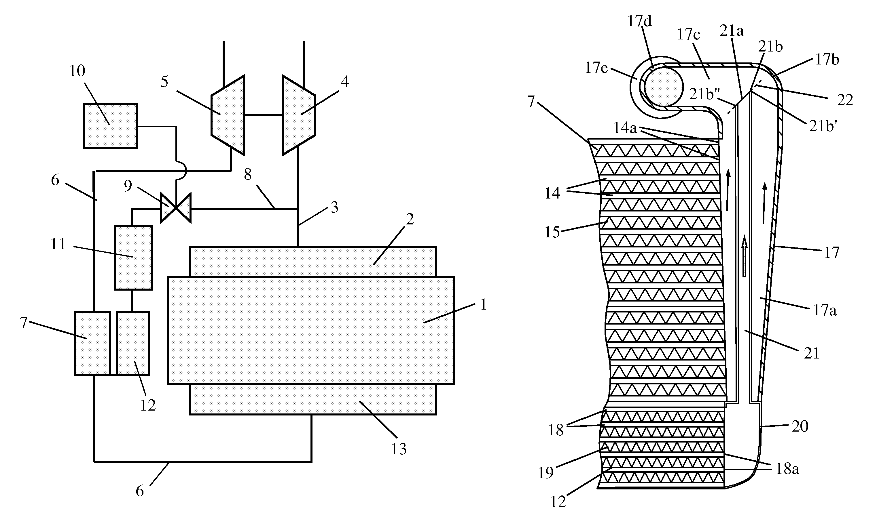
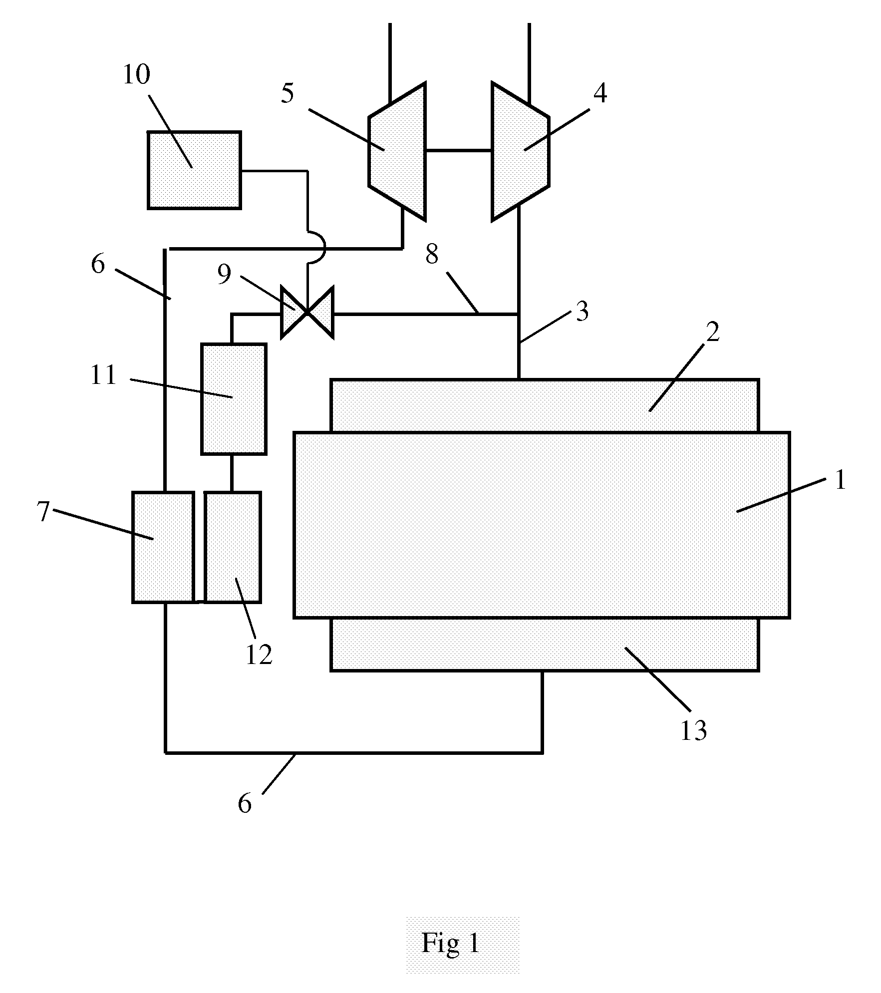
[0014]FIG. 1 depicts schematically an arrangement for recirculation of exhaust gases of a supercharged combustion engine. The combustion engine 1 may be an Otto engine or a diesel engine. Such recirculation of exhaust gases is called EGR (Exhaust Gas Recirculation). Adding exhaust gases to the compressed air which is led to the engine's cylinders lowers the combustion temperature and hence also the content of nitrogen oxides (NOx) formed during the combustion processes. The combustion engine 1 may for example be intended to power a heavy vehicle. The exhaust gases from the cylinders of the combustion engine 1 are led via an exhaust manifold 2 to an exhaust line 3. The exhaust gases in the exhaust line 3, which are at above atmospheric pressure, are led to a turbine 4. The turbine 4 is thus provided with driving power which is transferred, via a connection, to a compressor 5. The compressor 5 compresses the air which is led to the combustion engine 1 via an inlet line 6. A charge air...


PUM


Abstract

A cooler arrangement comprising a charge air cooler which comprises at least one first pipeline for guiding compressed air during cooling and a tank which receives the cooled compressed air via an outlet aperture from the first pipeline, and an EGR cooler which comprises at least one second pipeline for guiding exhaust gases during cooling and a tank which receives the cooled exhaust gases from an outlet aperture of the second pipeline. The cooler arrangement comprises a tubular element extending from the EGR cooler's tank to the charge air cooler's tank. The tubular element has an outlet aperture for exhaust gases which is situated downstream of the most downstream outlet aperture in the charge air cooler's tank with respect to the main direction of flow of the air in the tank.

Description

CROSS REFERENCE TO RELATED APPLICATION[0001]The present application is a 35 U.S.C. §§371 national phase conversion of PCT / SE2006 / 050199, filed 16 Jun. 2006, which claims priority of Swedish Application No. 0501403-0, filed 17 Jun. 2005. The PCT International Application was published in the English language.BACKGROUND TO THE INVENTION, AND STATE OF THE ART[0002]The present invention relates to a cooler arrangement for a combustion engine and particulary to separaying cooled exhaust gases and gases cooled in a charge air cooler.[0003]The amount of air which can be supplied to a supercharged combustion engine depends on the pressure of the air but also on the temperature of the air. Supplying the largest possible amount of air to the combustion engine therefore entails cooling the compressed air in a charge air cooler before it is led to the combustion engine. The compressed air is usually cooled by ambient air flowing through the charge air cooler. The compressed air can thus be cool...

Claims


Application Information

Patent Timeline
Patent Type & Authority Patents(United States)
IPC IPC(8): F02B29/04
CPCF02B29/0456F02B29/0475F02M25/0735F02M25/0736F28F19/00F28F21/083F28D1/0443F02M25/0707F02M25/0714Y02T10/121Y02T10/146F02M26/05F02M26/11F02M26/30F02M26/31Y02T10/12F02M26/09
Inventor KARDOS, ZOLTANNYREN, HENRIK
Owner SCANIA CV AB
Why Eureka
Try Eureka