Apparatus for heating liquid samples for analysis

a technology of apparatus and liquid sample, which is applied in the direction of lighting and heating apparatus, indirect heat exchangers, instruments, etc., can solve the problems of the inability to accurately measure the accuracy of high resolution instruments. , to achieve the effect of improving the residence time of air passing, improving the efficiency of cooling the air, and improving the accuracy of high resolution instruments

Active Publication Date: 2013-12-03
HORN JACK DELANEY JR
View PDF21 Cites 10 Cited by
  • Summary
  • Abstract
  • Description
  • Claims
  • Application Information

AI Technical Summary

Benefits of technology

[0014]The rinse systems preferably are driven by pressurized air which has been passed through a dryer to remove excess moisture from the air. Preferably, the dryer comprises a condenser assembly for removing humidity from pressurized air which has been constructed in accordance with other aspects of the subject invention. The novel condenser assemblies comprise a metallic condenser block which preferably is fabricated from at least two parts. The condenser block has a passageway which has an inlet and outlet, thus allowing pressurized air to be passed through the condenser block. The passageway defines an extended, serpentine course so as to increase the residence time of air passing through the condenser block and to allow more efficient cooling of the air. The condenser block also has a drain which allows moisture condensed in the block to flow therefrom.
[0015]A cooling element is mounted to the surface of the condenser block for absorbing heat from said condenser block. The cooling element preferably is a Peltier cooler. The condenser assembly also preferably includes a regulator in fluid communication with the condenser block for reducing the pressure of air discharged from the condenser.
[0016]It will be appreciated that the novel heater assemblies allow for effective, efficient, rapid, and easy control over the temperature of the heat sink assembly and, therefore, of samples loaded therein. Moreover, they allow for rapid and easy processing of different samples with a minimum of downtime.

Problems solved by technology

The accuracy of high resolution instruments, however, can be diminished by sample related effects.
Such properties, however, are temperature dependent.
Thus, if the temperature of samples is not carefully and reproducibly controlled, even the most sophisticated instrument will provide inaccurate and inconsistent measurements.
The analytical instruments themselves are capable of maintaining the temperature of a sample, but typically have relatively limited capacity to adjust sample temperatures rapidly.
When that happens the instrument may take a relatively long time to adjust the temperature of a sample.
The temperature of the heating block, however, can take a long time to adjust if the temperature must be lowered.
Moreover, sample fluids are loaded in vials, and thus the device cannot monitor the temperature of the sample directly.
Vial contamination also is a significant issue.
Cleaning and reusing vials may be difficult and time consuming.
It also can involve added expense, as will the use of single-use vials.
Fluid bath preheaters are widely used and are generally effective in bringing a sample to a desired temperature, but they suffer a number of deficiencies.
Bath fluids, or their additives, also can present safety issues if users are accidentally exposed to them, especially since the bath may be at elevated temperatures.
Moreover, bath preheaters require a relatively large supply of clean, uncontaminated vials, and because the sample is in a vial, it generally is not practical to measure the temperature of a sample directly.
The prior art, therefore, to date has failed to adequately and simultaneously address various issues relating to the performance, design, use, and fabrication of sample preheating devices.
Any delay in adjusting the temperature of samples in the preheater will cause a corresponding delay in the ultimate analysis of samples.

Method used


Image

  • Apparatus for heating liquid samples for analysis
  • Apparatus for heating liquid samples for analysis
  • Apparatus for heating liquid samples for analysis

Examples


Embodiment Construction

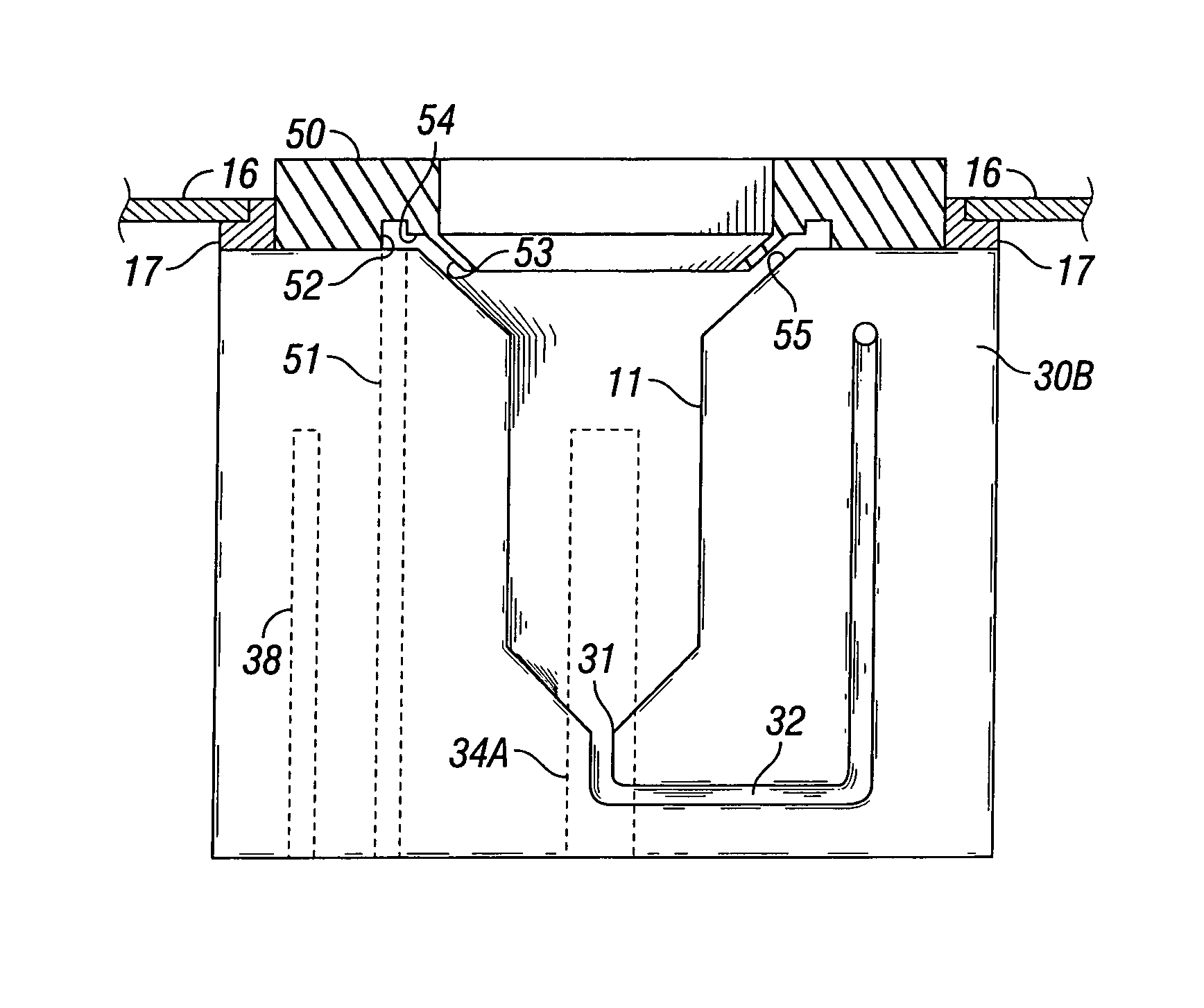
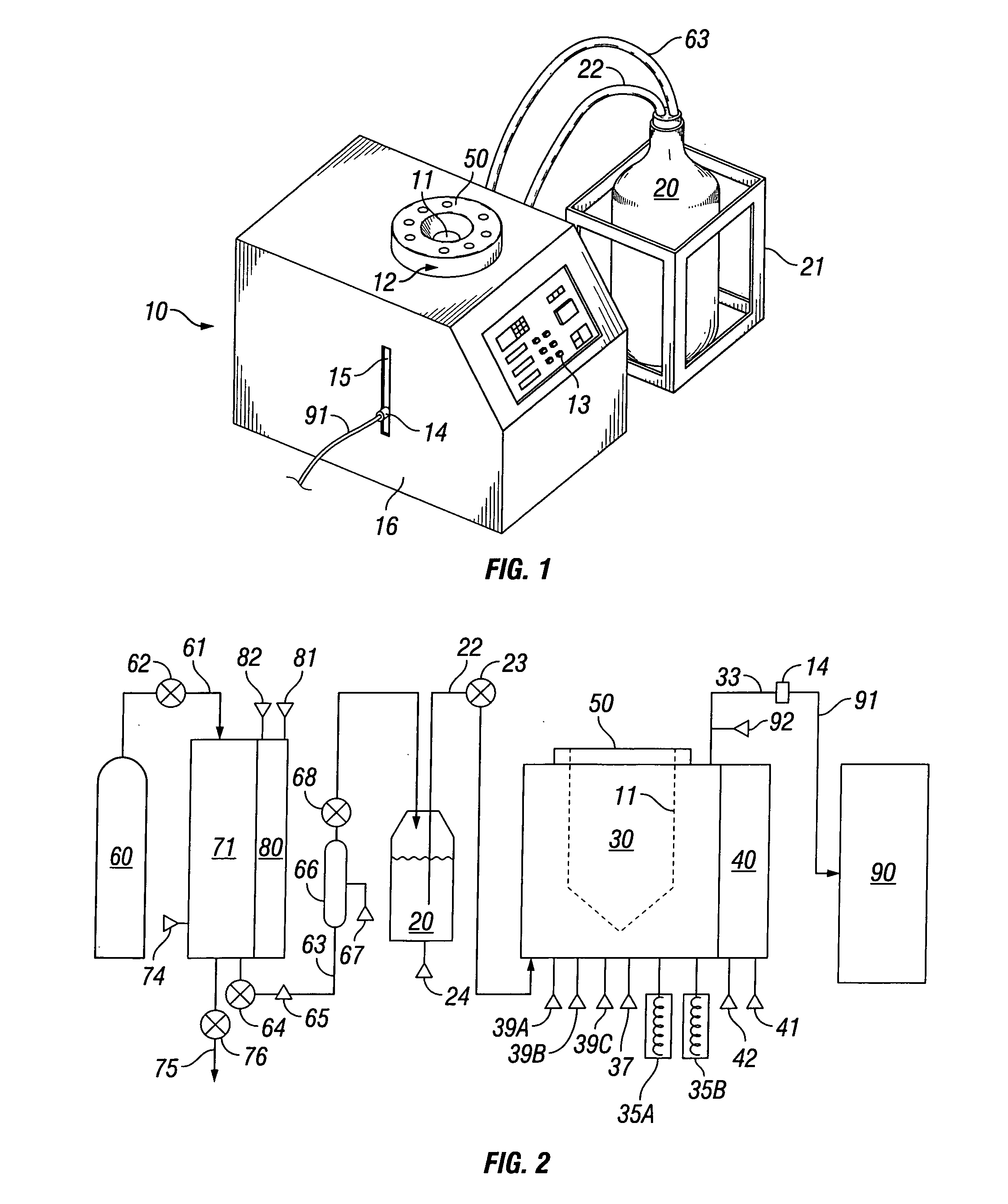
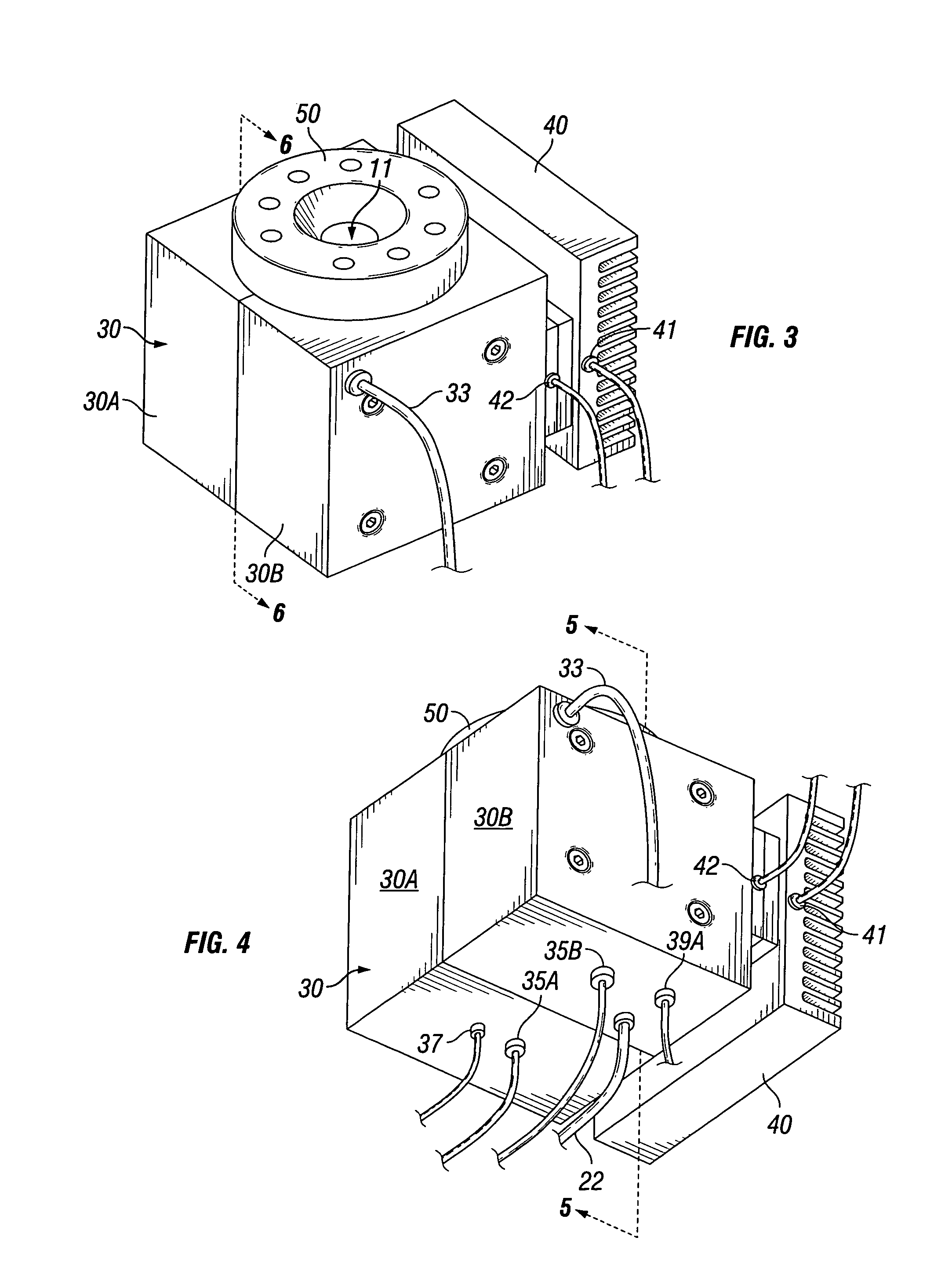
[0027]The heater assemblies of the subject invention, such as the preferred embodiment 10 and its various components illustrated in FIGS. 1-10, are intended for use in preheating liquid samples which will be introduced into an analytical instrument or other analytical streams. For example, as shown generally in the preferred sample preheater 10 shown in FIG. 1, liquid samples may be introduced into a sample basin 11 in a heat sink assembly 12 for preheating. Desired temperatures and other process parameters and operations may be set via a control panel 13. Once it has been preheated, the sample is withdrawn from sample basin 11 and fed into an analytical instrument, such as instrument 90 shown schematically in FIG. 2, via internal drains, passageways, and conduits (not shown in FIG. 1) and a sample discharge connection 14. Sample discharge connection 14 preferably is a standard threaded connection which is compatible with vacuum feed lines commonly used in analytical instruments so ...


PUM

PropertyMeasurementUnit
diameteraaaaaaaaaa
temperatureaaaaaaaaaa
pressureaaaaaaaaaa

Abstract

Heat sinks for use in assemblies for preheating liquid samples prior to their introduction into an analytical stream. The heater assemblies have a heat sink having a metallic heater block and a heating element for heating the block. The block has a basin for receiving a liquid sample and allowing heat to be transmitted from the block to the sample. A drain at the lower end of the basin allows sample in the basin to flow out of the basin. A passageway extends through the block from the drain to an exterior surface of the block and provides a conduit for sample flowing from the drain, A temperature sensor is mounted in a cavity in the block and extends into the basin to measure the temperature of sample in the basin. A temperature sensor is mounted in a cavity in the block and measures the temperature of the block.

Description

FIELD OF THE INVENTION[0001]The present invention relates to apparatus used to preheat liquid samples for analysis, and more particularly, to sample preheaters comprising improved heat sink assemblies and rinse systems.BACKGROUND OF THE INVENTION[0002]High resolution analytical instruments are capable of measuring the physical and chemical properties of materials with great accuracy. Such analysis plays an important role in modern manufacturing processes by ensuring that starting materials meet all required specifications. The accuracy of high resolution instruments, however, can be diminished by sample related effects.[0003]For example, it often is important to determine the density, refractive index, and other physical and chemical properties of liquids that will be used in a manufacturing process. Such properties, however, are temperature dependent. Thus, if the temperature of samples is not carefully and reproducibly controlled, even the most sophisticated instrument will provid...

Claims


Application Information

Patent Timeline
Patent Type & Authority Patents(United States)
IPC IPC(8): F28D15/00G01N1/22G01N1/00
CPCB01L7/00B01L99/00F28D2021/0028B01L2300/1805B01L2300/1822B01L2300/1827B01L2400/0487B01L13/02F25B21/04G01N1/22G01N2001/2282G01N1/28G01N1/42G01N35/1009G01N2001/002
Inventor HORN, JR., JACK DELANEYBARBER, RICKY WAYNE
Owner HORN JACK DELANEY JR
Why Eureka
Try Eureka