Aircraft vehicle centrifugal fan apparatus

a technology for centrifugal fans and aircraft, which is applied in the direction of vertical landing/taking-off aircraft, aircraft navigation control, transportation and packaging, etc., can solve the problems that light aircraft have not applied the advanced characteristics of their larger jet propelled designs, and achieve high volume flow and pressure characteristics, superior low-noise operation, and high volume of air

Inactive Publication Date: 2013-12-03
CARAMBAT DAVID
View PDF36 Cites 33 Cited by
  • Summary
  • Abstract
  • Description
  • Claims
  • Application Information

AI Technical Summary

Benefits of technology

[0012]The present invention provides a craft, such as an aircraft or hovercraft that features a fabric fan that provides a high volume of air for lift and propulsion and using a quieter alternative to the much noisier axial propeller. Centrifugal ...

Problems solved by technology

Light aircraft have not applied the advanced c...

Method used


Image

  • Aircraft vehicle centrifugal fan apparatus
  • Aircraft vehicle centrifugal fan apparatus
  • Aircraft vehicle centrifugal fan apparatus

Examples


Embodiment Construction

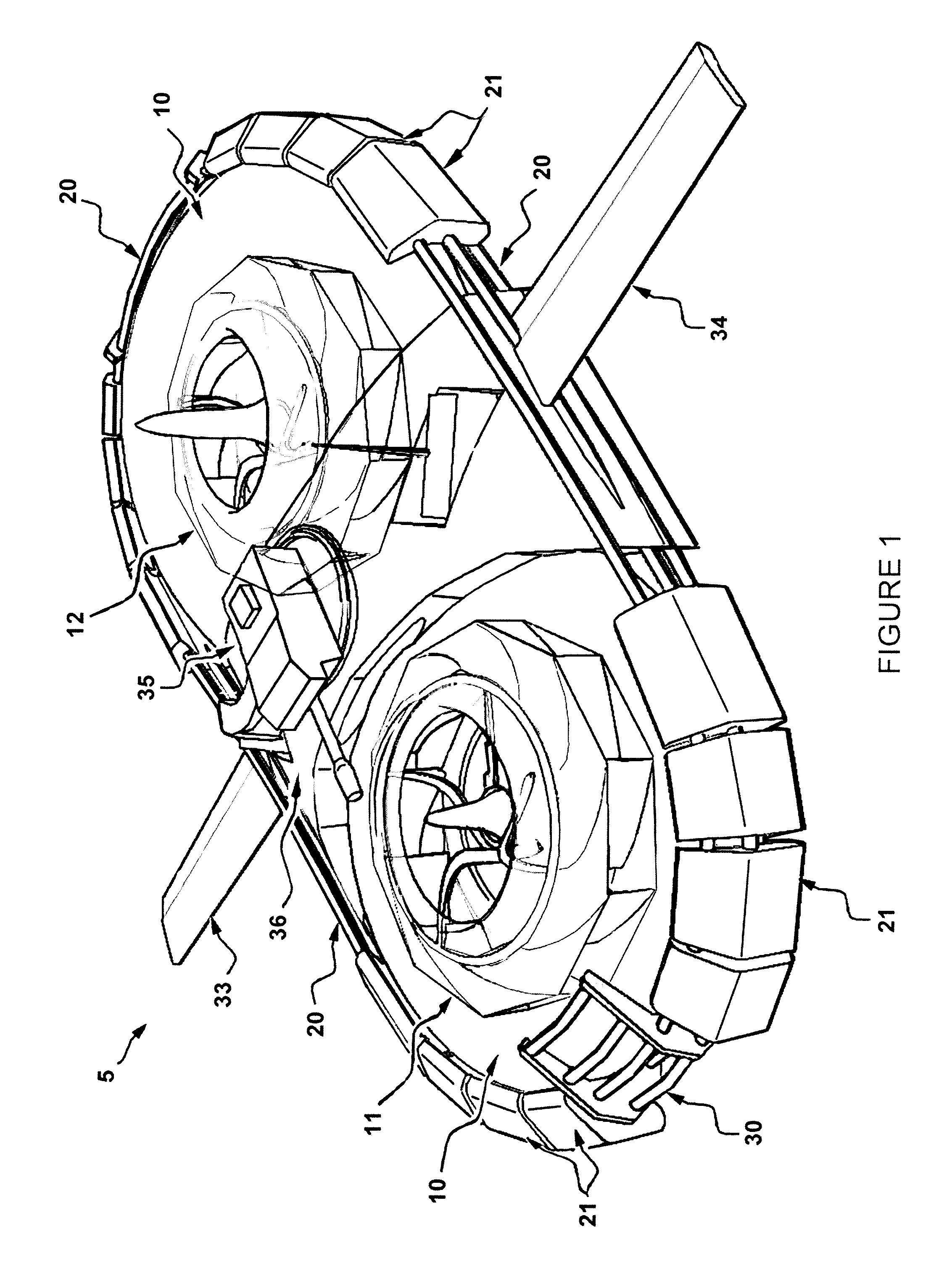
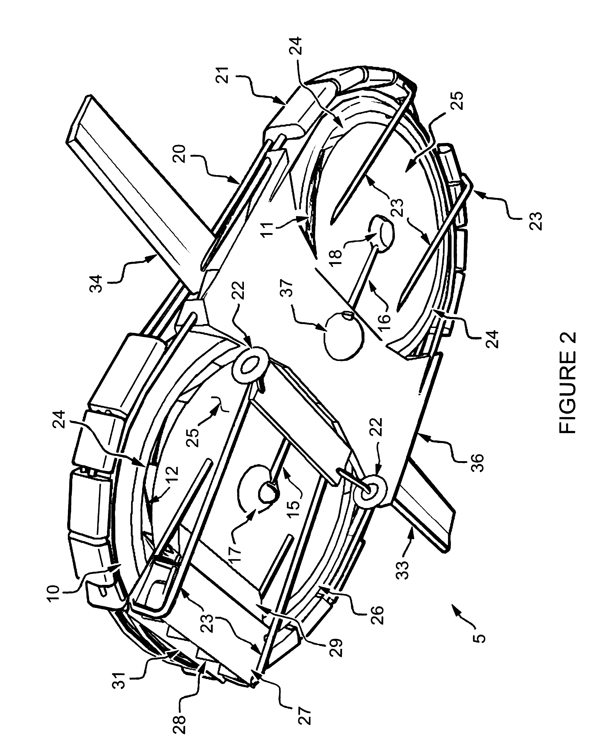
[0047]FIGS. 1-5 show generally the preferred embodiment of the apparatus of the present invention, designated generally by the numeral 5 (FIGS. 1, 2) 6 (FIG. 3), 7 (FIG. 4), and 8 (FIG. 5).

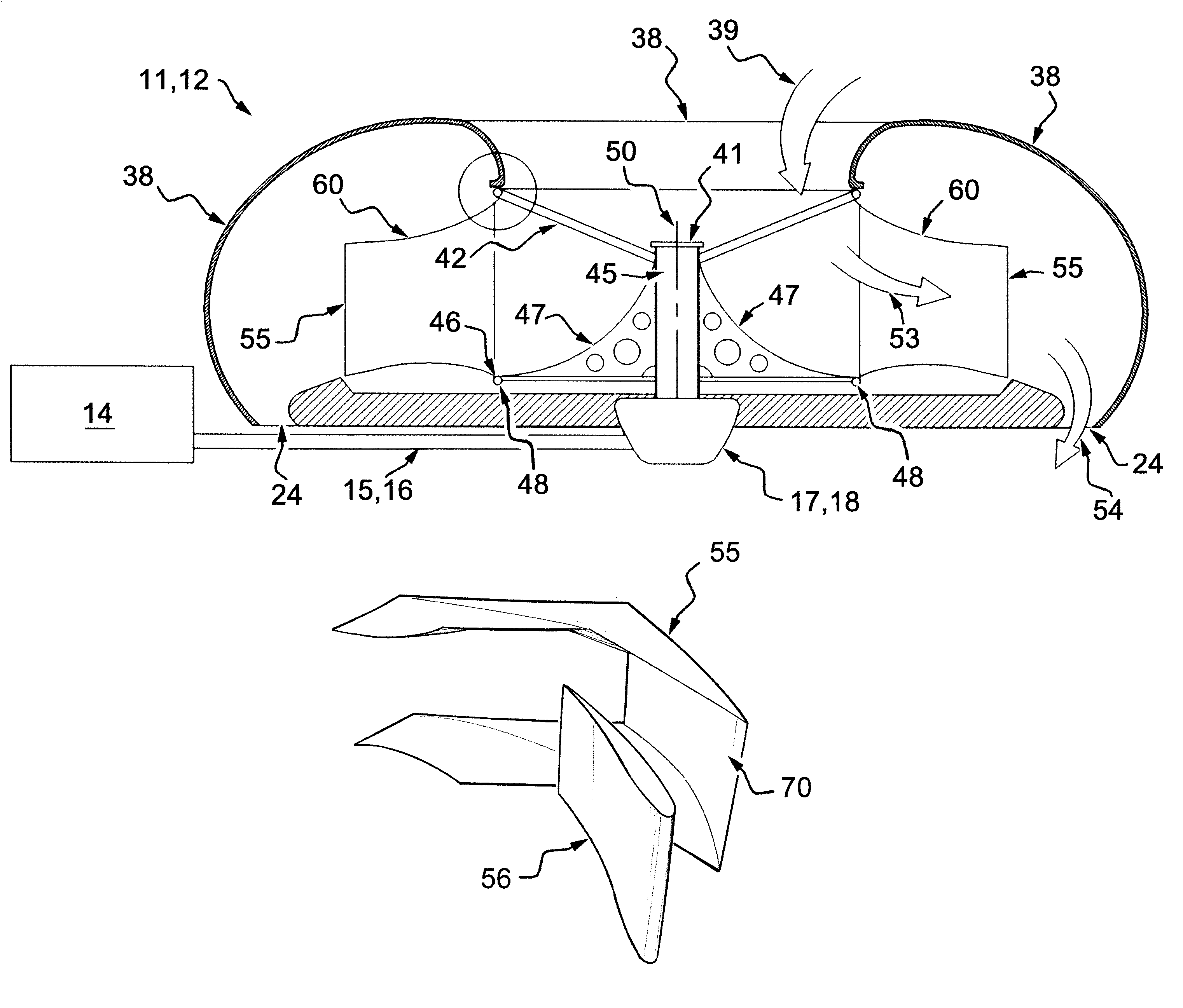
[0048]Aircraft 5 of FIGS. 1, 2 is shown in a dual fan, longitudinal layout. This layout allows maximum lift while minimizing frontal area. The aircraft 5 can be an unmanned aerial vehicle or manned aircraft having a body or fuselage 10 with dual fabric fans 11, 12. Each fan 11, 12 can be shaft driven by a central mounted motor or engine 14, shafts 15, 16 and angle gearboxes 17, 18. These fore and aft fabric fans 11, 12 provide pressurized air flow for dynamic lift and thrust. The aircraft air-flow is distributed by an enclosed duct within the body shell 10.

[0049]The lightweight body / shell 10 can be surrounded by a structure such as a rigid alloy pipe structure 20 which holds strategically placed bumpers 21 (e.g. foam). Manual movement and landing can be supported by wheels 22 and forward and rear ...


PUM


Abstract

An aircraft provides hovercraft power via fabric fans that produce lift for supporting the craft above an underlying support surface. Fabric fans are specially configured for maximum efficiency. In one embodiment, a helicopter utilizes the fan as part of a tail rotor assembly.

Description

CROSS-REFERENCE TO RELATED APPLICATIONS[0001]Priority of U.S. Provisional Patent Application Ser. No. 61 / 445,431, filed Feb. 22, 2011, incorporated herein by reference, is hereby claimed.STATEMENT REGARDING FEDERALLY SPONSORED RESEARCH OR DEVELOPMENT[0002]Not applicableREFERENCE TO A “MICROFICHE APPENDIX”[0003]Not applicableBACKGROUND OF THE INVENTION[0004]1. Field of the Invention[0005]The present invention relates to a craft such as a hovercraft that employs one or more specially configured hovercraft fans.[0006]2. General Background of the Invention[0007]There is a growing demand for quieter and more efficient aircraft and unmanned aerial vehicles or unmanned aerial vehicles or UAV's. Until now the centrifugal fan has been overlooked due to the heavy solid construction required for stability of the fans complex geometry.[0008]The original hovercraft engineers in the late 1960's used a type of centrifugal fan as the best solution for the needs of that unique aircraft. However they...

Claims


Application Information

Patent Timeline
IPC IPC(8): B64C29/00
CPCB64C11/006B64C11/20B60V1/00B64C27/82B64C29/0025B64C2027/8254B64U70/80B64U50/14B64U10/10B64U60/60B64U20/30B64U30/294
Inventor CARAMBAT, DAVID
Owner CARAMBAT DAVID
Why Eureka
Try Eureka