Wide band embedded armor antenna

an armor antenna and wide band technology, applied in the field of armor antennas, can solve the problems of the greatest challenge in antenna design, the undesirable forest of antennas that extend from armored vehicles, etc., and achieve the effect of reducing vswr and maximizing gain

Active Publication Date: 2013-12-03
BAE SYST INFORMATION & ELECTRONICS SYST INTERGRATION INC
View PDF7 Cites 15 Cited by
  • Summary
  • Abstract
  • Description
  • Claims
  • Application Information

AI Technical Summary

Benefits of technology

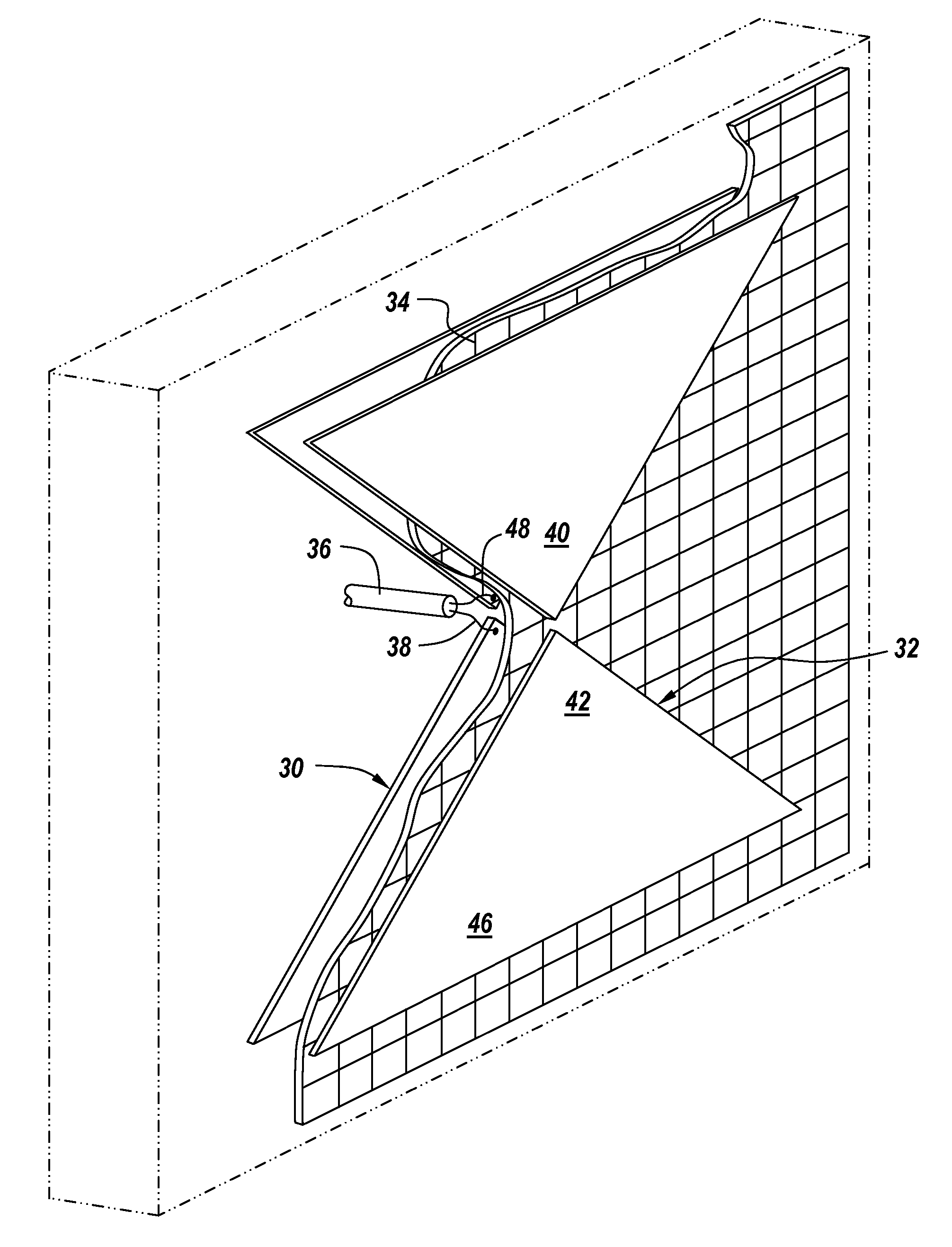
[0009]It has been found that it is possible to completely quantify the electromagnetic characteristics of the armor materials to a result it has been found that one can establish the permittivity and loss of each piece of the armor recipe that affects the effective electrical length and efficiency of the radiating structure. This being said, the dielectric constants of overlying or intermediate materials can be tailored to reduce VSWR and maximize gain and that this can be accomplished by completely characterizing the boundaries between the layers within the armor as well as the boundary to the outside or free space.

Problems solved by technology

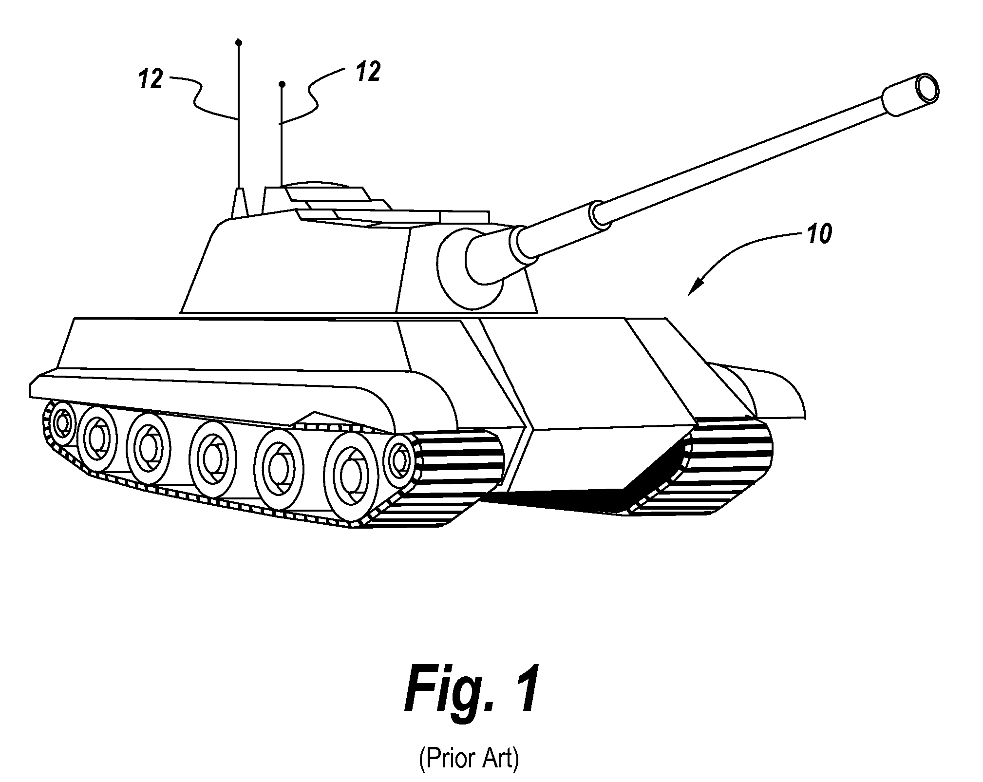
Having a forest of antennas that extend from the armored vehicle is undesirable because they are susceptible to damage and attack.
It is noted that the thin structure of present armor panels presents the greatest challenge to antenna design.

Method used


Image

  • Wide band embedded armor antenna
  • Wide band embedded armor antenna
  • Wide band embedded armor antenna

Examples


Embodiment Construction

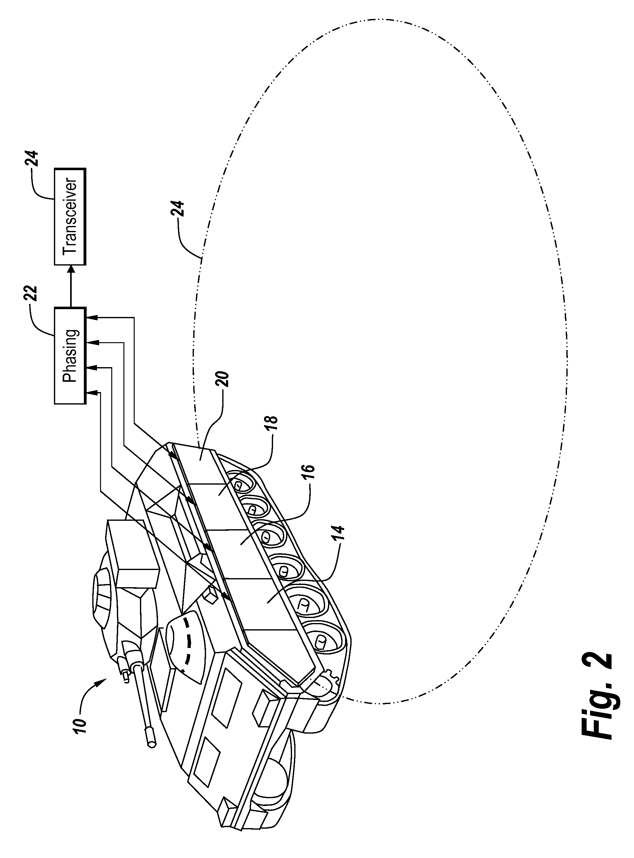
[0026]Prior to discussion of the specifics of the subject antenna system, it is noted that the thin structure of the armor panel is the greatest challenge to the antenna design. Whether the panel is metal-backed itself or is mounted on a metal vehicle, the close proximity of a conductive surface creates a groundplane to the radiating element. A conventional design would have the groundplane spaced at least a quarter-wavelength away. However, one is typically dealing with spacing more on the order of hundredths of a wavelength. It has been found that this is not a disqualifying factor in antenna designs. The present antenna array had a goal of creating thin antenna structures that do not rely on deep cavities behind the elements to integrate an antenna with the armor on a vehicle.

[0027]Being able to completely quantify the electromagnetic characteristics of the armor materials is essential to making accurate predictions of antenna performance. The permittivity and loss of each piece ...


PUM


Abstract

An extremely thin embedded antenna for an armor-carrying vehicle utilizes a dipole driven element to the inside of the armor plate and a parasitically-driven dipole element on top of the armor plate, with the parasitic element providing appropriate forward gain and antenna matching characteristics such that there need be no aperturing of the armor plate in order to feed the antenna. In one embodiment, the bowtie antenna elements are elongated, extended or expanded by outboard antenna sections which are spaced from the distal ends of the corresponding bowties, with a meanderline choke bridging the gap between a bowtie element and its extended portion.

Description

RELATED APPLICATIONS[0001]This application claims rights under 35 USC §119(e) from U.S. Application Ser. No. 61 / 486,956 filed May 17, 2011, the contents of which are incorporated herein by reference.FIELD OF THE INVENTION[0002]This invention relates to an antenna utilized on armored vehicles and more particularly to an armor-embedded parasitically-fed antenna system.BACKGROUND OF THE INVENTION[0003]As described in provisional patent application 61 / 486,956 filed May 17, 2011, it is desirable to provide a thin structure for an antenna embedded in an armor panel and more particularly to provide a parasitic element on top of the armor layer so that when driving the antenna there are no apertures in the armor which would degrade performance. In one embodiment the aperture-less embedded antenna system includes a direct fed dipole on the underneath side of the armor layer such that the armor layer is not pierced. There is an identical dipole on the top of the armor layer that is parasitica...

Claims


Application Information

Patent Timeline
Patent Type & Authority Patents(United States)
IPC IPC(8): H01Q1/32
CPCH01Q1/3291H01Q3/26H01Q5/378H01Q9/28H01Q9/145
Inventor APOSTOLOS, JOHN T.MOUYOS, WILLIAMLAPIERRE, RANDALL R.
Owner BAE SYST INFORMATION & ELECTRONICS SYST INTERGRATION INC
Why Eureka
Try Eureka