
System and method for measuring fatigue for mechanical components of an aircraft and aircraft maintenance method

Active Publication Date: 2013-12-03
SN DETUDE & DE CONSTR DE MOTEURS DAVIATION S N E C M A
View PDF27 Cites 82 Cited by
  • Summary
  • Abstract
  • Description
  • Claims
  • Application Information

AI Technical Summary

Benefits of technology

The goal of this invention is to make it easier to measure the fatigue of airplane components and improve their overhauls and usage.

Problems solved by technology

Finally, in the absence of analysis of the real stresses to which a component has been subjected, the worst case scenario is always taken with respect to the possible damaging of the latter, which leads to overhauls that are often premature.
Moreover, and for safety reasons, the components are used for a shorter period than they could actually be, so that they do not achieve periods of use during which the risk of breakage exceeds a certain threshold.
Moreover, because of the frequent overhauls (making it necessary to remove the suspension from an airplane and then to reinstall it on an airplane that is a priori different) and different service lives of the various components of an airplane, the monitoring of the service life of a suspension is complex.
In particular, it may happen that the serial number etched on a metal suspension wears off over time; in this case, not being able to refer to its history and in order to take no risk, the estimate of its period of use must be made with the most pessimistic assumptions, for example considering that this suspension was installed in the first airplane fitted with this type of suspension and has flown continuously since then; in practice, the use of the component has been less than this pessimistic notional assumption such that the suspension will be replaced too soon.
Moreover, although there currently exist indirect indicators of the fatigue of suspensions, they can only be approximate and provide uncertain information.
Nevertheless, although a hard landing may indeed impose exceptional loads on a suspension, it is not systematically the case and one may be induced to overhaul a suspension when the landing has not actually stressed the suspension, for example because the forces have been absorbed and have not been transmitted to the suspension.

Method used


Image

  • System and method for measuring fatigue for mechanical components of an aircraft and aircraft maintenance method
  • System and method for measuring fatigue for mechanical components of an aircraft and aircraft maintenance method
  • System and method for measuring fatigue for mechanical components of an aircraft and aircraft maintenance method

Examples


Embodiment Construction

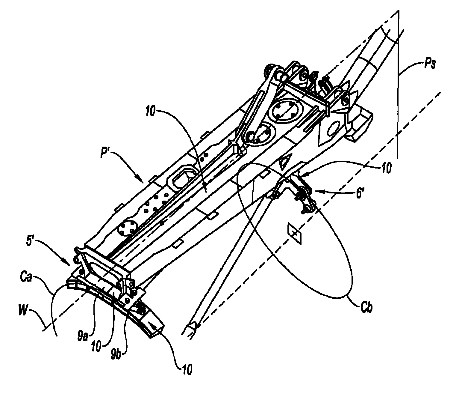
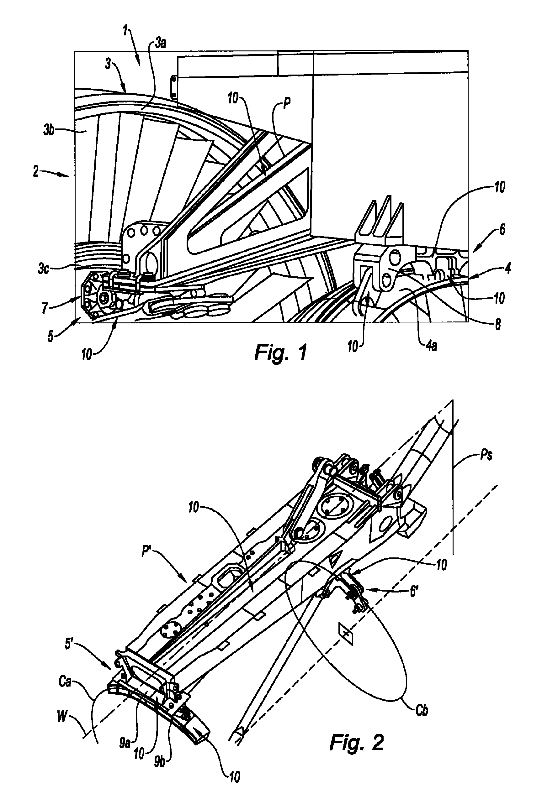
[0054]With reference to FIG. 1, and in a manner well known to those skilled in the art, a turbojet 1 comprises a fan 2 by which the outside air is aspirated into the turbojet, a low-pressure compressor upstream of a high-pressure compressor, these compressors being arranged to compress the air and at the exit of which the compressed air is guided to a combustion chamber where it is burnt with fuel that is also compressed; the burnt gases are guided to a high-pressure turbine then a low-pressure turbine at the exit of which they are expelled from the turbojet through an exhaust nozzle.

[0055]The various portions of the turbojet are contained in casings. The turbojet 1 shown in FIG. 1 comprises in particular, upstream, a fan casing and a casing 3 called the intermediate casing and, downstream, an exhaust casing 4. The intermediate casing 3 and the exhaust casing 4 are structural casings of the structure of the turbojet 1.

[0056]The intermediate casing 3 comprises an external shroud 3a c...


PUM


Abstract

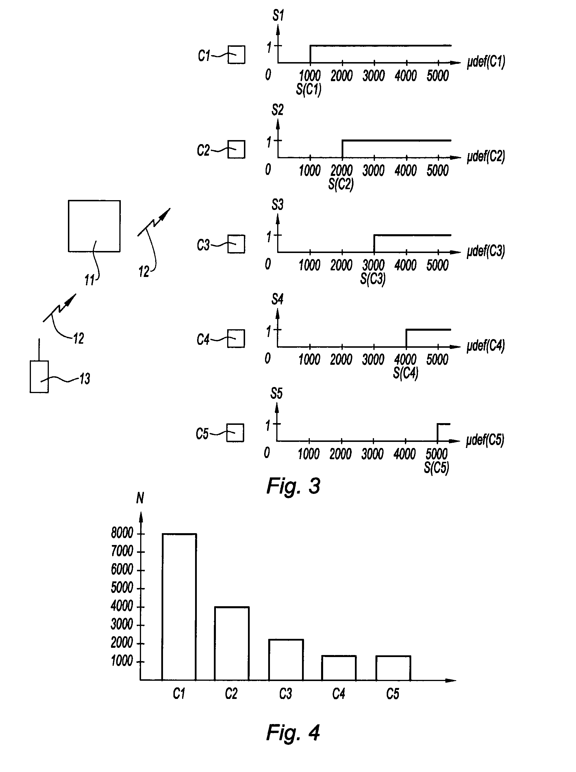
A system for measuring fatigue of a component of an aircraft subject to mechanical stresses includes: a plurality of stress sensors mounted on the component, each sensor being configured to detect a predetermined mechanical stress threshold and to deliver a data signal representative of exceeding of the threshold; and a mechanism for recording the data and the sensors configured to detect different stress thresholds so as to make it possible to calculate, on the basis of the data recorded by the system, an estimation of fatigue of the component due to the mechanical stresses. It is thus possible to optimize overhaul of the components.

Description

BACKGROUND OF THE INVENTION[0001]1. Field of the Invention[0002]The invention relates to a system and a method for measuring fatigue for mechanical components of an aircraft, for example an airplane, and a method for maintaining the aircraft.[0003]Safety rules require airlines to monitor the fatigue of the components of the aircraft that they operate, these components being subjected to a large number of mechanical stresses (or loads). The components are therefore the subject of an overhaul (or maintenance) in a regular and recurrent manner.[0004]2. Description of the Related Art[0005]For example, the components for suspending the turbojets from the airplanes are subjected to strict inspections. Each overhaul of a suspension makes it necessary to stop the operation of the airplane and to remove the suspension in order to carry out the tests. The frequency of the overhauls is determined in advance and an overhaul is carried out systematically on expiration of each preset time period ...

Claims


Application Information

Patent Timeline
IPC IPC(8): G01B7/16
CPCG01M5/0033G01N3/32G07C5/0841G01N2203/0073G01N2203/0286G07C5/006
Inventor SEIZE, GUILHEM
Owner SN DETUDE & DE CONSTR DE MOTEURS DAVIATION S N E C M A
Learn More