Fuel cell system

a fuel cell and system technology, applied in the direction of electric energy management, feeding apparatus, dc source parallel operation, etc., can solve the problem of reducing the output electric power, and achieve the effect of reducing the efficiency of the fuel cell system and restraining the loss of switching

Active Publication Date: 2013-12-10
TOYOTA JIDOSHA KK
View PDF55 Cites 10 Cited by
  • Summary
  • Abstract
  • Description
  • Claims
  • Application Information

AI Technical Summary

Benefits of technology

[0052]The fuel cell system according to the present invention determines whether or not the voltage of the electric power supplied from the fuel cell maintains the voltage necessary for driving the drive motor in order to establish the consistency between ensuring the stable drive of the drive motor and ameliorating the efficiency of the fuel cell system, or properly determines the timing when the boost device boosts the output voltage of the fuel cell, thus gets the boost device to adequately perform the boost operation, and can scheme to restrain the switching loss due to the boost device.

Problems solved by technology

The fuel cell outputs the electric power in response to a request of a drive motor by controlling a quantity of supply of fuel gas, however, there is a case in which responsibility of the output electric power decreases due to a delay of response of the gas supply quantity, and a secondary battery might be mounted for compensation thereof.

Method used


Image

  • Fuel cell system
  • Fuel cell system
  • Fuel cell system

Examples


first working example

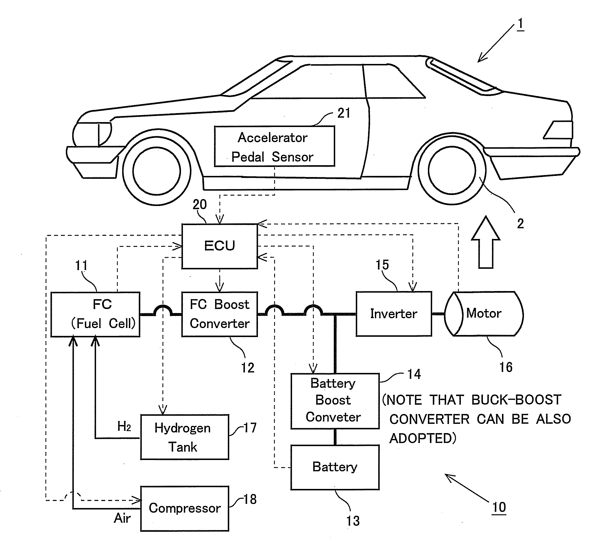
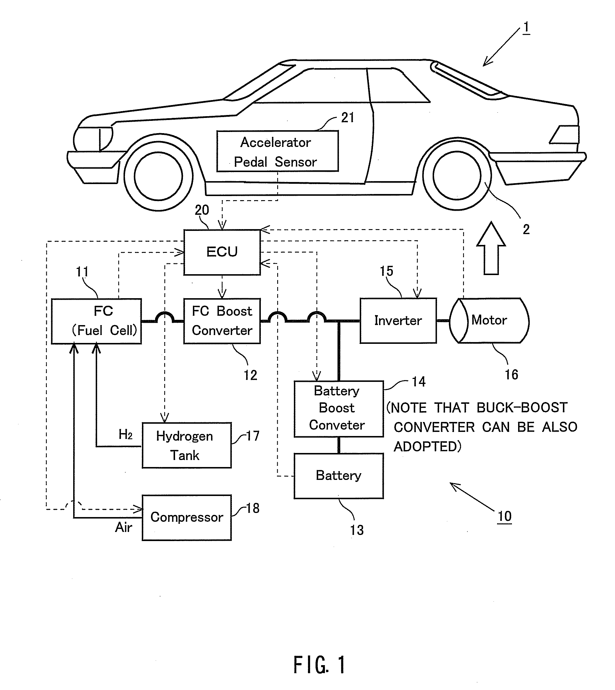
[0104]FIG. 1 schematically illustrates an outline of a configuration of the fuel cell system 10 according to the present invention and the vehicle 1 of the movable body of which a drive source is the electric power supplied from the fuel cell system 10. Drive wheels 2 are driven by the drive motor (which will hereinafter simply be referred to as the [motor]) 16, whereby the vehicle 1 drives itself and thus gets movable. This motor 16 is a so-called three-phase AC (Alternating Current) motor and supplied with AC power from an inverter 15. Further, this inverter 15 is supplied with DC (Direct Current) power from a fuel cell (which is also abbreviated to [FC]) 11 defined as a main power source of the fuel cell system 10 and from a battery 13 defined as a secondary battery, and the supplied DC power is converted into the alternating current (AC) by the inverter 15.

[0105]Herein, the fuel cell 11 generates the electricity with electrochemical reaction between a hydrogen gas reserved in a ...

second working example

[0155]A second working example of the fuel cell system 10 according to the present invention will be discussed. One example of how the FC boost converter 12 is controlled in order to enhance the efficiency of the fuel cell system 10 will be described based on FIG. 11B. The FC boost converter control shown in FIG. 11B is executed when the ECU 20 supplies the motor 16 with the electric power generated by the fuel cell 11. Processes S501-S504 in the FC boost converter control shown in FIG. 11B are the same as the processes S201-S204 in the FC boost converter control shown in FIG. 11A, and hence their descriptions are herein omitted. When a process in the process S504 in the FC boost converter control shown in FIG. 11B is terminated, the operation proceeds to S505.

[0156]In S505, the output voltage of the fuel cell 11 is calculated based on the output of the fuel cell 11 (which will hereinafter be simply referred to as the FC output). The FC output is calculated according to the formula ...

first modified example

[0165]Moreover, it is preferable that the converting efficiency of the inverter 15 and the efficiency of actuating the motor 16 are taken into consideration with respect to applying the voltage to the inverter 15 for actuating the motor 16. For example, as explained in the first working example and the second working example given above, when supplying the power to the motor 16 from the fuel cell 11, the FC boost converter 12 is not sopped, in which case the voltage applied to the inverter 15 is boosted by the FC boost converter 12. In the first modified example, the voltage applied to the inverter is determined from a map in which the efficiency characteristic of the loads including the inverter 15 and the motor 16 is associated with the voltage applied to the inverter 15 on the basis of the request torque and the number of revolutions of the motor 16. Then, with the boost operation of the FC boost converter 12, the output voltage of the fuel cell 11 is boosted up to the thus-deter...


PUM

PropertyMeasurementUnit
currentaaaaaaaaaa
speedaaaaaaaaaa
voltageaaaaaaaaaa

Abstract

In order to assure drive of a drive motor, a boost operation of a boost device is appropriately performed by judging whether a voltage supplied from a fuel cell suffices a voltage required for driving the drive motor, thereby suppressing a switching loss by the boost device. A fuel cell system is a power source for driving a load. The system includes: a drive motor driven by an electric power; a fuel cell which generates electricity by an electrochemical reaction between an oxidizing gas containing oxygen and a fuel gas containing hydrogen and supplies an electric power to the drive motor; a first boost device which can boosts the voltage outputted from the fuel cell and supplies the boosted voltage to the drive motor; and boost control means which controls voltage boost performed by the first boost device according to the relationship between the fuel cell output voltage and the voltage required by the drive motor.

Description

CROSS-REFERENCE TO RELATED APPLICATIONS[0001]This application is the national phase application under 35 U.S.C. §371 of PCT international application No. PCT / JP2008 / 073772 filed on 26 Dec. 2008, which claims the benefit of priority of the prior Japanese Patent Applications No. 2007-341267, filed on 28 Dec. 2007, and No. 2007-341288, filed on 28 Dec. 2007, the entire contents of which are incorporated herein by reference.FIELD OF THE INVENTION[0002]The present invention relates to a fuel cell system which supplies a drive motor with electric power from a fuel cell generating the electric power with electrochemical reaction.BACKGROUND OF THE INVENTION[0003]Over the recent years, a fuel cell has been focused as a power source that is excellent in terms of operation efficiency and environmentality. The fuel cell outputs the electric power in response to a request of a drive motor by controlling a quantity of supply of fuel gas, however, there is a case in which responsibility of the out...

Claims


Application Information

Patent Timeline
Patent Type & Authority Patents(United States)
IPC IPC(8): H01M8/04H02J7/00B60L11/18
CPCB60L1/003B60L11/1803B60L11/1887H01M8/04559H01M8/04619H01M8/0488H01M10/44H02M1/34H02M3/158B60L2210/14B60L2240/12B60L2240/423B60W10/08B60W10/26B60W10/28H01M2250/20H01M2250/402H02M2001/342Y02B90/12Y02E60/50Y02T90/32Y02T90/34Y02T10/7225Y02T10/642B60L2240/527B60L50/51B60L58/40Y02B90/10Y02T10/64Y02T10/72Y02T90/40Y02T10/70Y02E60/10H02M1/342
Inventor HAMADA, KENICHIKITAMURA, NOBUYUKIMANABE, KOUTAIMANISHI, HIROYUKI
Owner TOYOTA JIDOSHA KK
Why Eureka
Try Eureka