
Thermal tracking for solar systems

a solar system and tracking technology, applied in the field of sensors and feedback systems, can solve problems such as high cost of cameras, low accuracy, and low accuracy, and achieve the effects of reducing efficiency by over 10%, reducing the cost of cameras, and reducing the accuracy of measuremen

Inactive Publication Date: 2013-12-10
SUNPOWER CORPORATION
View PDF89 Cites 35 Cited by
  • Summary
  • Abstract
  • Description
  • Claims
  • Application Information

AI Technical Summary

Benefits of technology

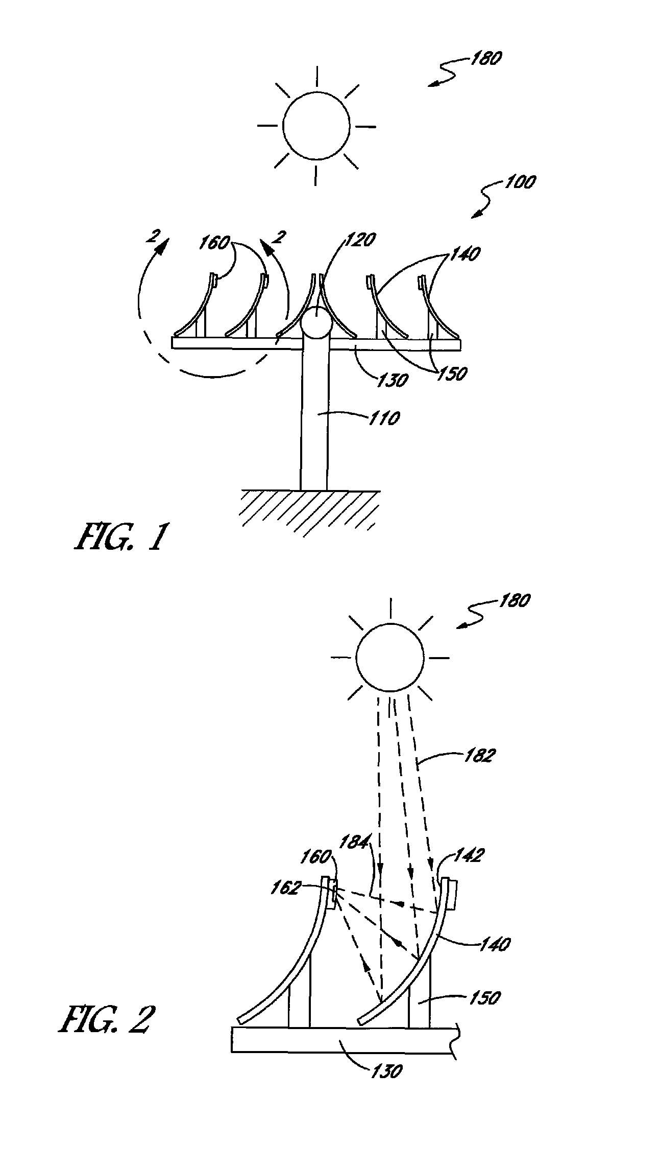
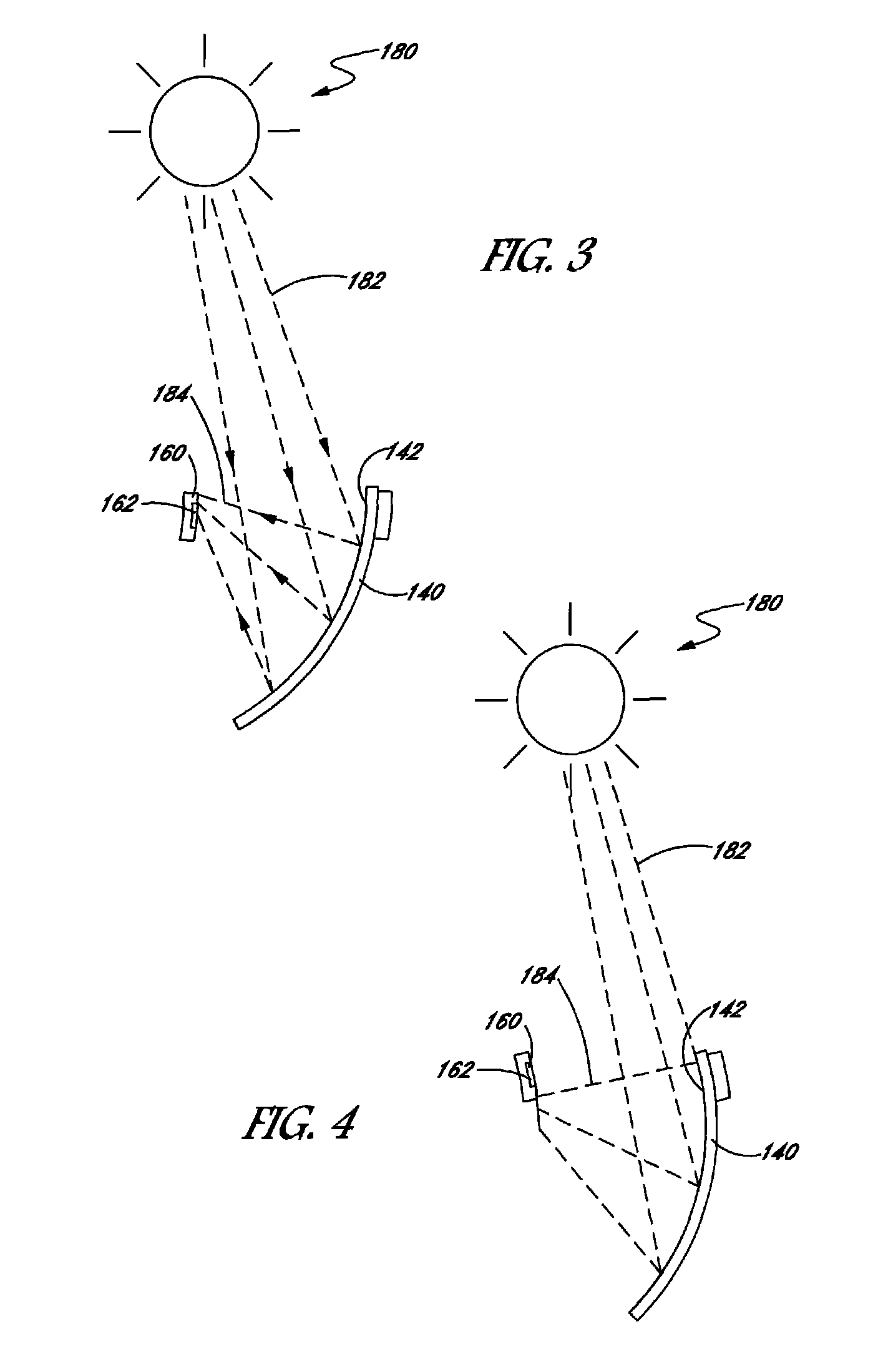
This patent describes a power generating system that uses a solar cell and a support structure to adjust its position. The system includes two thermal sensors that detect temperature on the solar cell at different locations. The control system receives signals from these sensors and adjusts the position of the solar cell accordingly. This allows the system to track the sun and increase its efficiency. The technical effects of this patent are improving the positioning of a solar cell to optimize its performance and increasing the efficiency of a power generating system.

Problems solved by technology

Some sources of alignment error can be caused, for example, by inaccurate site location, contributions from an inclinometer, motor encoder, or other positioning equipment error.
Although seemingly small, a single degree of alignment error can translate into an efficiency decrease of over 10%, particularly when aligning a solar concentrating system.
Cameras are, however, typically expensive, and can require extensive and sophisticated signal processing to determine a precise solar position.
Additionally, the camera element will encounter environmental effects which can decrease its efficacy as a sensor.
Moreover, imprecision in mounting the camera also can result in alignment error.
High speed electronics, which can be expensive, are required to perform the rapid inspection needed to determine the optimum alignment profile.
Additionally, small changes in irradiance due to clouds or air masses can produce a condition similar to a misalignment condition, thereby confusing the tracker.
Consequently, the tracker can introduce erroneous misalignment, thereby reducing efficiency.
Current tracking systems, therefore, can be expensive, introduce misalignment error even under optimal conditions, and can have sensitive components exposed to detrimental environmental conditions.

Method used


Image

  • Thermal tracking for solar systems
  • Thermal tracking for solar systems
  • Thermal tracking for solar systems

Examples


Embodiment Construction

[0026]The following detailed description is merely illustrative in nature and is not intended to limit the embodiments of the subject matter or the application and uses of such embodiments. As used herein, the word “exemplary” means “serving as an example, instance, or illustration.” Any implementation described herein as exemplary is not necessarily to be construed as preferred or advantageous over other implementations. Furthermore, there is no intention to be bound by any expressed or implied theory presented in the preceding technical field, background, brief summary or the following detailed description.

[0027]Techniques and technologies may be described herein in terms of functional and / or logical block components and with reference to symbolic representations of operations, processing tasks, and functions that may be performed by various computing components or devices. In practice, one or more processor devices can carry out the described operations, tasks, and functions by m...


PUM


Abstract

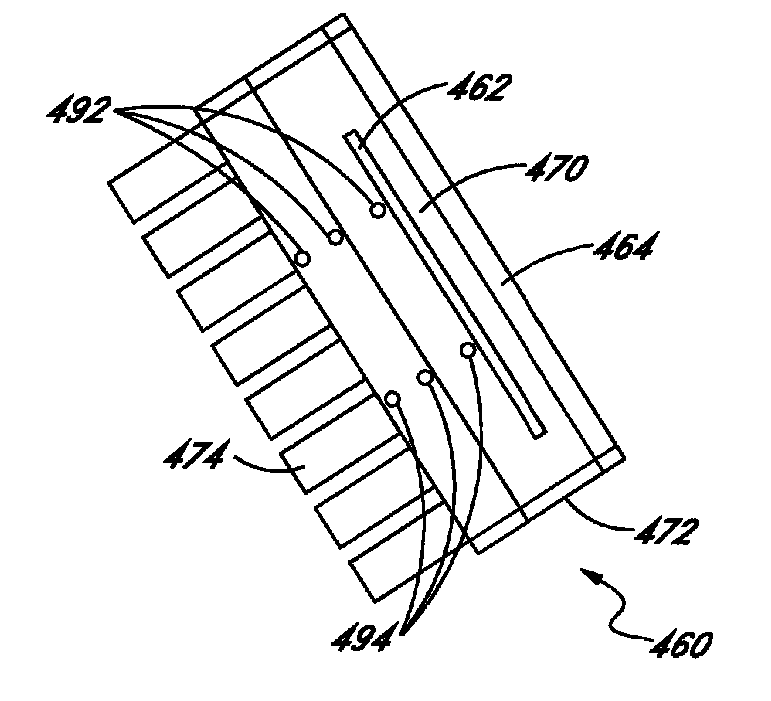
A power generating system is disclosed. The power generating system comprises a solar cell, a support structure coupled to the solar cell and adapted to adjust the position of the solar cell, a first thermal sensor coupled to the solar cell and adapted to detect a first temperature at a first location on the solar cell, a second thermal sensor coupled to the solar cell and adapted to detect a second temperature at a second location on the solar cell, the second location spaced apart from the first location, and a control system. The control system is adapted to receive a first signal from the first thermal sensor and a second signal from the second thermal sensor, compare information conveyed in the first and second signals, and adjust the position of the solar cell by operating the support structure in response to information conveyed in the first and second signals.

Description

TECHNICAL FIELD[0001]Embodiments of the subject matter described herein relate generally to sensing and feedback systems. More particularly, embodiments of the subject matter relate to tracking systems for solar panels.BACKGROUND[0002]Solar systems which track apparent movement of the sun across the sky during the day typically use sensors to determine the position of the sun and adjust the solar system accordingly. A variety of techniques are currently used to operate solar systems. For example, sun position tables generated from known longitude and latitude can be used to predict the location of the sun during the course of the day. The deviation between predicted and actual position can be significant. Some sources of alignment error can be caused, for example, by inaccurate site location, contributions from an inclinometer, motor encoder, or other positioning equipment error. Although seemingly small, a single degree of alignment error can translate into an efficiency decrease o...

Claims


Application Information

Patent Timeline
IPC IPC(8): G01C21/02H01L31/042F24S20/20F24S23/74F24S50/20
CPCH01L31/0525H01L31/0547F24J2/402F24J2/14F24J2/38F24J2/07Y02E10/52Y02E10/47H02S20/32H01L31/048F24S20/20F24S23/74F24S50/20F24S50/40Y02E10/40
Inventor LINDERMAN, RYAN J.
Owner SUNPOWER CORPORATION
Learn More