Inspection device and inspection method for inspecting magnetic disk or magnetic head

a technology of inspection device and inspection method, which is applied in the direction of digital signal error detection/correction, instruments, recording signal processing, etc., can solve the problems of position information demodulation errors, the accuracy of servo pattern demodulation, and the speed of eccentricity correction, so as to improve the accuracy of position signal detection and reduce the demodulation errors of servo demodulation circuit.

Inactive Publication Date: 2013-12-10
HITACHI HIGH-TECH CORP
View PDF9 Cites 0 Cited by
  • Summary
  • Abstract
  • Description
  • Claims
  • Application Information

AI Technical Summary

Benefits of technology

[0009]It is therefore the primary object of the present invention to provide an inspection device and an inspection method for inspecting a magnetic disk or a magnetic head capable of realizing reduction of the position information demodulation errors caused by the eccentricity of the magnetic disk and improvement of the position signal detection accuracy, as well as enabling quick eccentricity clock correction for arbitrary clock frequencies.
[0012]According to the present invention, the position information demodulation errors of the servo demodulation circuit are reduced and the position signal detection accuracy is improved even when there exists the disk eccentricity. Further, quick eccentricity clock correction becomes possible for arbitrary clock frequencies. With these effects, high-accuracy and high-performance inspection device and inspection method for inspecting a magnetic disk or a magnetic head can be provided.

Problems solved by technology

However, the JP,A 6-223502 has not considered a quick processing method for the eccentricity correction in regard to arbitrary disk revolution speeds and arbitrary servo pattern frequencies.
Meanwhile, the JP-A-2010-49775 has not considered the accuracy of the servo pattern demodulation when there is a disk eccentricity.
Therefore, if a disk eccentricity exists when the servo pattern format or the disk revolution speed varies, the eccentricity correction can not be made quickly, causing the position information demodulation errors and deterioration in the position signal detection accuracy.

Method used


Image

  • Inspection device and inspection method for inspecting magnetic disk or magnetic head
  • Inspection device and inspection method for inspecting magnetic disk or magnetic head
  • Inspection device and inspection method for inspecting magnetic disk or magnetic head

Examples


Embodiment Construction

[0023]Referring now to the drawings, a description will be given in detail of a preferred embodiment in accordance with the present invention.

[0024]First, the servo pattern on a magnetic disk to be processed in the present invention will be explained below.

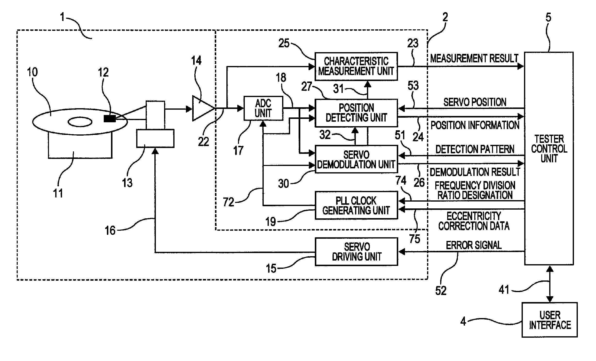
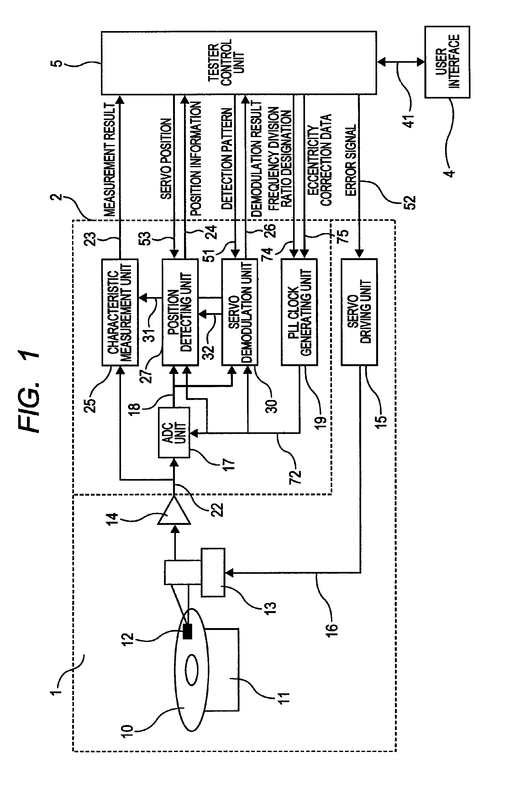
[0025]FIG. 10 is a schematic diagram showing an example of the servo pattern written on a magnetic disk. A plurality of tracks 10t are formed as concentric circles on a disk surface of the magnetic disk 10. Each track includes a plurality of servo areas (servo sectors) 10s and data areas which are used for the actual data recording / reproduction. The reference character “12” represents a magnetic head and “14” represents an amplifier for amplifying a read signal. While the servo information format in the servo areas 10s varies depending on the HDD maker and the HDD type, a typical example is shown in FIG. 10. The area “PA” (Preamble Field) is used for preparation till the reading of the servo areas. A waveform with a single frequen...


PUM

PropertyMeasurementUnit
frequencyaaaaaaaaaa
data densityaaaaaaaaaa
revolution speedsaaaaaaaaaa

Abstract

The present invention realizes reduction of position information demodulation errors caused by the eccentricity of the magnetic disk and improvement of position signal detection accuracy, as well as enabling quick eccentricity clock correction for arbitrary clock frequencies. An inspection device in accordance with the present invention comprises: a servo demodulation unit which demodulates servo information; a PLL clock generating unit which generates a reference clock and supplies the reference clock to the servo demodulation unit; and a tester control unit. The PLL clock generating unit includes an eccentricity correction circuit for correcting the frequency of the reference clock depending on the eccentricity of the magnetic disk. The tester control unit generates correction data for correcting the frequency of the reference clock, multiplies the correction data by the inverse of a transfer function of the PLL clock generating unit, and supplies the product to the eccentricity correction circuit.

Description

CLAIM OF PRIORITY[0001]The present application claims priority from Japanese patent application serial No. JP2011-076646, filed on Mar. 30, 2011, the content of which is hereby incorporated by reference into this application.BACKGROUND OF THE INVENTION[0002](1) Field of the Invention[0003]The present invention relates to an inspection device and an inspection method for inspecting a magnetic disk or a magnetic head, and in particular, to an inspection device and an inspection method capable of conducting the inspection with high accuracy even when the format of the servo pattern written on the magnetic disk varies.[0004](2) Description of the Related Art[0005]Magnetic disks to which the servo pattern has previously been written by stamper technology and microscopic processing technology (e.g., nano-printing) for realizing high data density (DTM (Discrete Track Media), BPM (Bit Patterned Media), magnetic transfer media, etc.) are becoming the mainstream of the magnetic disks for HDDs...

Claims


Application Information

Patent Timeline
Patent Type & Authority Patents(United States)
IPC IPC(8): G11B27/36
CPCG11B5/59627G11B20/10222G11B2220/2516
Inventor SAKURAI, YOSHIHIROHIGA, KUNIHITOYAMAMOTO, YUKIO
Owner HITACHI HIGH-TECH CORP
Why Eureka
Try Eureka