Anchoring of septums in acoustic honeycomb

a technology of acoustic honeycomb and septum, which is applied in the field of acoustic systems, can solve the problems of limited strength of structure, add these thin and flexible acoustic materials, and limit the bonding surface between the two honeycomb slices, so as to improve the utilization of material and friction-locking the septum, and reduce the cost of rework

Active Publication Date: 2013-12-17
HEXCEL
View PDF26 Cites 21 Cited by
  • Summary
  • Abstract
  • Description
  • Claims
  • Application Information

AI Technical Summary

Benefits of technology

[0009]In accordance with the present invention, it was discovered that the orientation of the septum fabric within the honeycomb cell is an important factor that determines how well the septum friction-locks to the walls of the honeycomb. The invention is applicable to honeycomb cells that include at least two parallel walls where at least one of the parallel walls forms a greater portion of the cell perimeter than one or more of the other non-parallel walls. It was discovered that orienting the septum material, such that the fibers extending between the two parallel walls are substantially perpendicular to the walls, provides an effective way to friction-lock the septum to the honeycomb. The present invention improves material utilization and friction-locking of the septum to the honeycomb. The invention substantially reduces rework costs and inconvenience due to septums falling out of the honeycomb or otherwise shifting during handling prior to and during adhesive application.
[0012]The present invention is also directed to the precursor structures that are formed when the septum is friction-locked within the honeycomb cell. It was discovered that the friction-locking provided by the perpendicular orientation of the septum fibers in accordance with the present invention prevents shifting of the septums within the honeycomb during all phases of routine handling of the precursor structure prior to and during permanent bonding of the septums to the honeycomb. The present invention is further directed to methods for making acoustic structures.
[0013]The present invention provides a number of advantages in addition to secure friction-locking of the septum to the core. For example, the amount of septum material is reduced because the same degree of friction-locking can be achieved with smaller sized anchoring portions. In addition, less material is wasted when the septum is cut from the septum fabric. Further, less folding of the septum material occurs when the septum is inserted into the cell because the size of the anchoring portion can be reduced and the perpendicular orientation of the fabric tends to reduce the extra mesh formation at the fold. The perpendicular fiber orientation within the cell also tends to reduce bunching of the septum material in the cell corners. The amount of adhesive needed to bond the septum to the honeycomb wall is also reduced due to the smaller anchoring portions and reduced fabric bunching. The septum can also be placed closer to the honeycomb edge, since the anchoring portions do not need to be as long in order to achieve adequate friction-locking. This is particularly advantageous for thin honeycomb where the size of the septum anchoring portion may approach the thickness of the honeycomb.

Problems solved by technology

One particularly problematic noise source is the jet engine used on most passenger aircraft.
The basic problem that faces engineers is how to add these thin and flexible acoustic materials into the structural elements of the jet engine and surrounding nacelle to provide desired noise attenuation.
However, a drawback of this design is that the strength of the structure is limited by the bond between the two honeycomb slices and the acoustic material.
Also, the bonding surface between the two honeycomb slices is limited to the surface area along the edges of the honeycomb.
In addition, there is a chance that some of the holes in the acoustic material may be unintentionally closed with excess adhesive during the bonding process.
However, this approach also has a few drawbacks.
For example, the cost and complexity of having to drill millions of holes in the solid inserts is a major drawback.
In addition, the relatively thick solid inserts make the honeycomb stiff and difficult to form into non-planar structures, such as nacelles for jet engines.
The septums may shift or otherwise move during handling if friction-locking is not adequate.
Any shifting of the septums makes it difficult to apply adhesive uniformly to the septums during bonding.
Shifting of the septums also causes uncontrolled altering of the acoustic properties.
In the worst case, the septum may fall completely out of the honeycomb cell if friction locking is not adequate.

Method used


Image

  • Anchoring of septums in acoustic honeycomb
  • Anchoring of septums in acoustic honeycomb
  • Anchoring of septums in acoustic honeycomb

Examples


Embodiment Construction

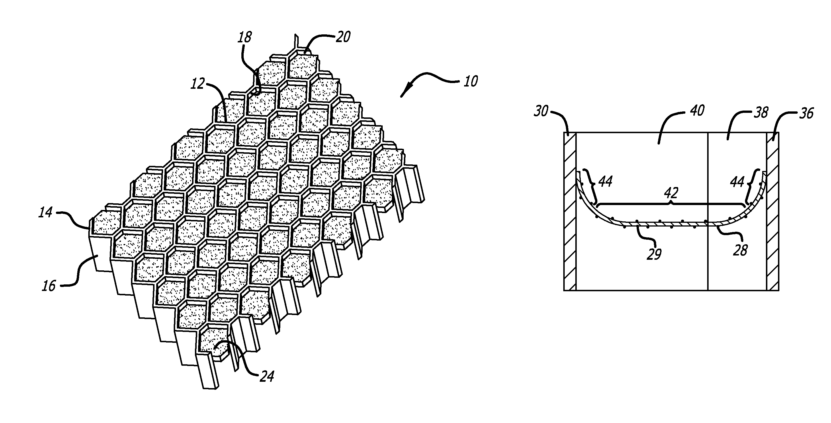
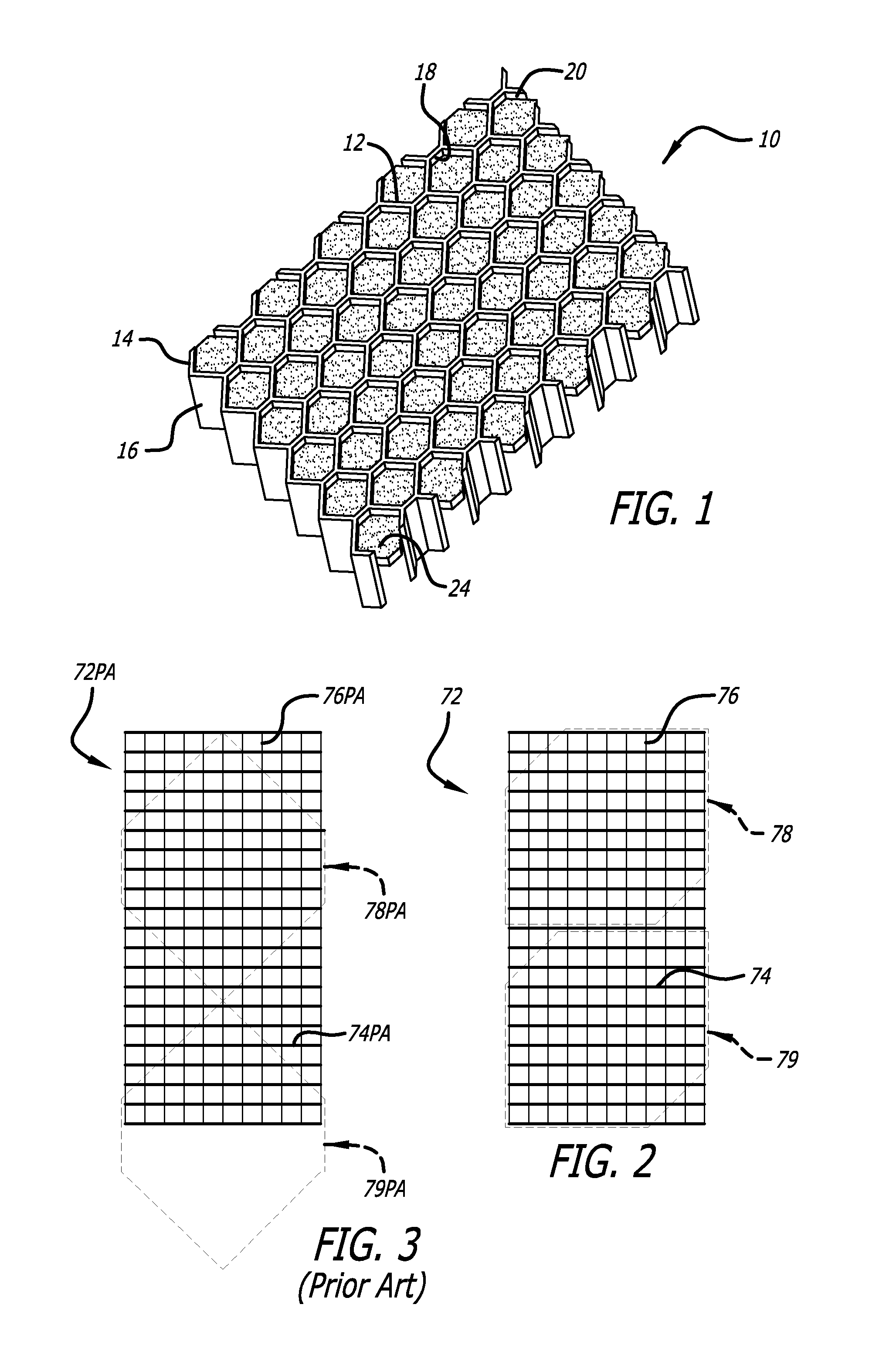
[0028]An exemplary acoustic structure in accordance with the present invention is shown generally at 10 in FIGS. 1 and 8. The acoustic structure 10 includes a honeycomb 12 having a first edge 14 which is to be located nearest the noise source and a second edge 16. The honeycomb 10 includes walls 18 that extend between the two edges 14 and 16 to define a plurality of cells 20. Each of the cells 20 has a depth (also referred to as the core thickness) that is equal to the distance between the two edges 14 and 16. Each cell 20 also has a cross-sectional area that is measured perpendicular to the cell walls 18. The honeycomb can be made from any of the conventional materials used in making honeycomb panels including metals, ceramics, and composite materials.

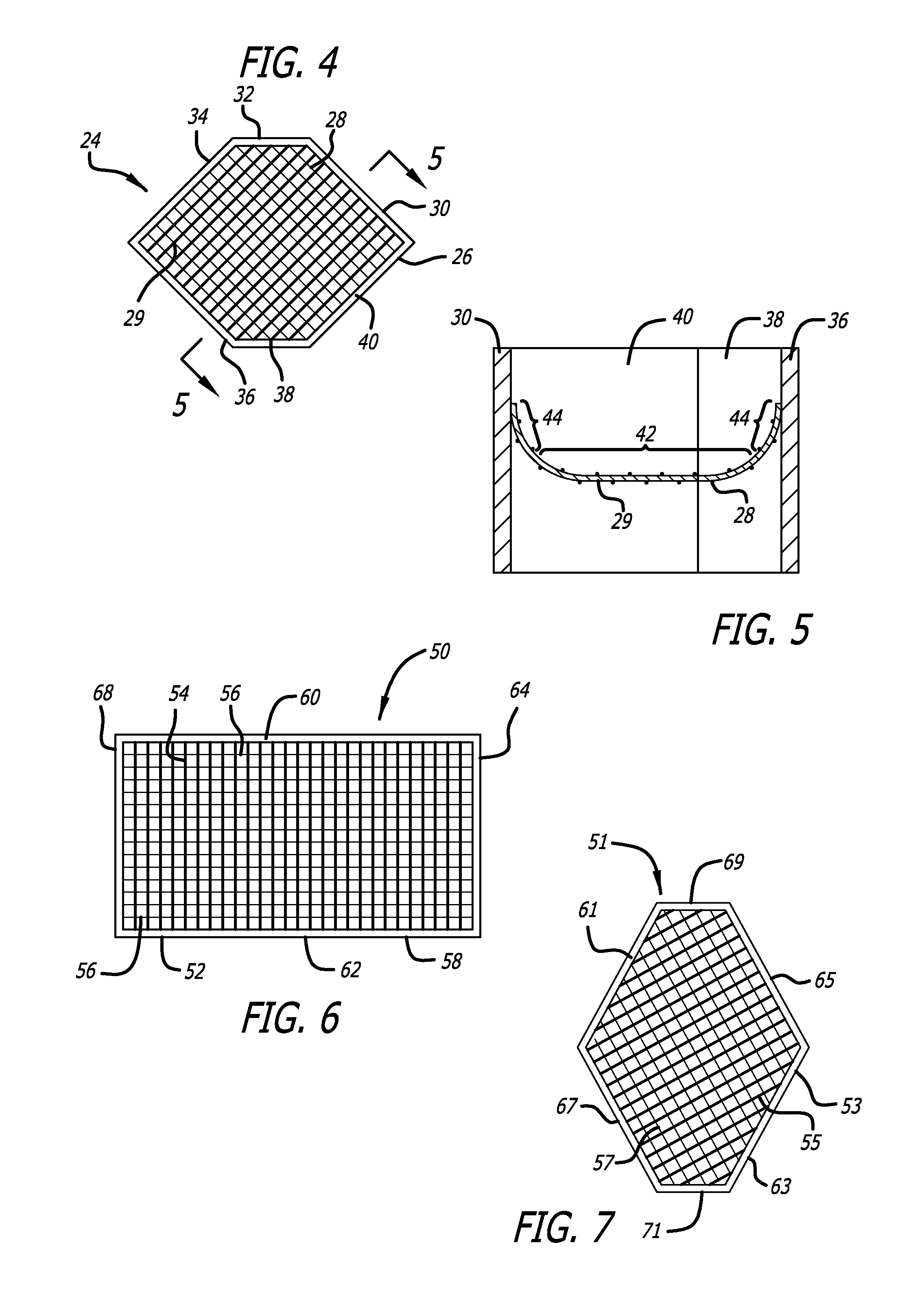
[0029]Septums 24 are located within the cells 20. It is preferred, but not necessary, that the septums 24 be located in most, if not all, of the cells 20. In certain situations, it may be desirable to insert the septums 24 in only som...


PUM

PropertyMeasurementUnit
angleaaaaaaaaaa
angleaaaaaaaaaa
angleaaaaaaaaaa

Abstract

A honeycomb structure that includes cells in which septums are located to provide acoustic dampening. The cells are formed by at least four walls wherein at least two of the walls are substantially parallel to each other. The septums include warp fibers and weft fibers that are substantially perpendicular to each other. The septums are oriented in the honeycomb cells such that the weft fibers and / or warp fibers are substantially perpendicular to the parallel walls.

Description

BACKGROUND OF THE INVENTION[0001]1. Field of the Invention[0002]The present invention relates generally to acoustic systems that are used to attenuate noise. The invention involves using honeycomb to make nacelles and other structures that are useful in reducing the noise generated by aircraft engines or other noise sources. More particularly, the invention is directed to acoustic structures in which septum material is inserted into the cells of pre-existing honeycomb to provide dampening or attenuation of noise.[0003]2. Description of Related Art[0004]It is widely recognized that the best way of dealing with excess noise generated by a specific source is to treat the noise at the source. This is typically accomplished by adding acoustic damping structures (acoustic treatments) to the structure of the noise source. One particularly problematic noise source is the jet engine used on most passenger aircraft. Acoustic treatments are typically incorporated in the engine inlet, nacelle a...

Claims


Application Information

Patent Timeline
Patent Type & Authority Patents(United States)
IPC IPC(8): E04B1/84B64C1/40E04B1/82
CPCG10K11/172G10K11/162E04B2001/748Y10T29/49801Y10T29/4957
Inventor ICHIHASHI, FUMITAKA
Owner HEXCEL
Why Eureka
Try Eureka