Thermal Curing of Cell-Based Structural Arrays

a technology of cell-based arrays and structural arrays, which is applied in the manufacture and reworking of cell-based arrays, can solve the problems of uneven heating of individual cells, non-uniform heat conduction, and internal sections of cell-based arrays heating up more slowly, and achieves easy manufacturing, reduced fabrication and rework costs, and high yield.

Active Publication Date: 2014-11-20
THE BOEING CO
View PDF7 Cites 6 Cited by
  • Summary
  • Abstract
  • Description
  • Claims
  • Application Information

AI Technical Summary

Benefits of technology

[0008]The disclosed embodiments provide a high yield, low-cost method and apparatus for thermally curing adhesives used to fabricate or rework cell-based structural arrays, such as those employed for structural RF apertures. Consistent, uniform heating of adhesive bondlines in each cell of the array is achieved using a combination of convection and conduction heating. Warm air is convected evenly across a bank of tools placed in the cells, and the heated tools uniformly conduct heat into each cell to cure the adhesive. The tools are simple and easily fabricated. Improved, uniform curing provided by the disclosed embodiments reduce fabrication and rework costs, while increasing production yields and decreasing cure times. The embodiments are well suited for uniform heating of large area cell arrays. Equipment costs may be reduced through the use of fewer thermocouples needed for monitoring cure temperatures, and use of less costly and / or less precise cure ovens.

Problems solved by technology

The curing technique described above relies on convection heat sources which may not evenly convect heat across the bank of tooling blocks.
This uneven convection heating is due in part to thermal gradients caused by the relatively high thermal mass of the tooling blocks.
Uneven convection heating may result interior sections of the cell-based array heating up more slowly than the outer sections.
Additionally, uneven heating may occur within the individual cells where the tooling blocks have insufficient thermal conductivity to conduct heat uniformly through the interior of the cells.
Again, this non-uniform heat conduction, particularly in remote regions of the tooling blocks, is due to the relatively high thermal mass of the tooling blocks.
As a result of these causes of uneven cell heating, the bonding adhesive may not be cured with sufficient uniformity across all cells of the array to meet process specifications, resulting in scrap or rework which adds to manufacturing costs.

Method used


Image

  • Thermal Curing of Cell-Based Structural Arrays
  • Thermal Curing of Cell-Based Structural Arrays
  • Thermal Curing of Cell-Based Structural Arrays

Examples


Embodiment Construction

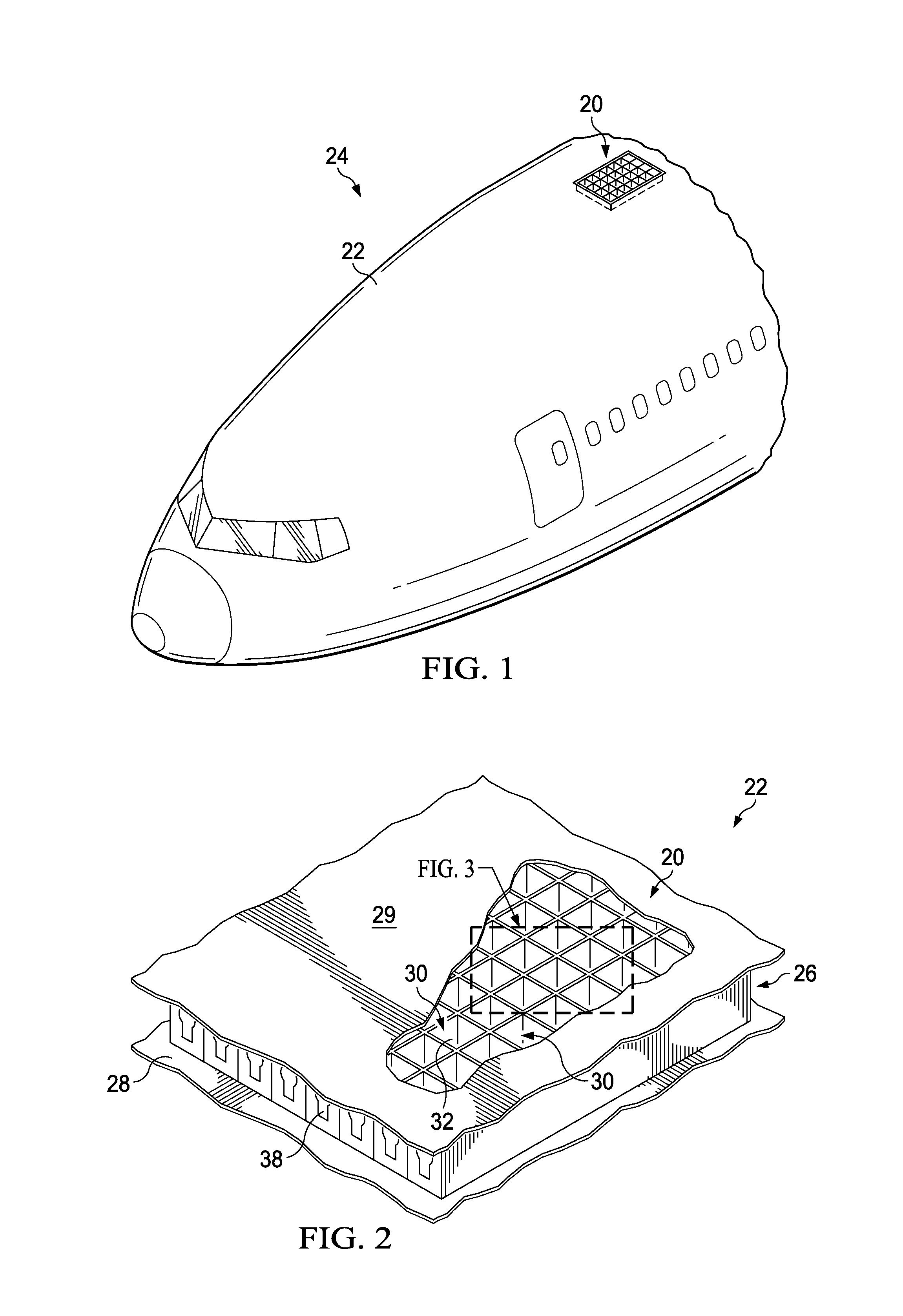
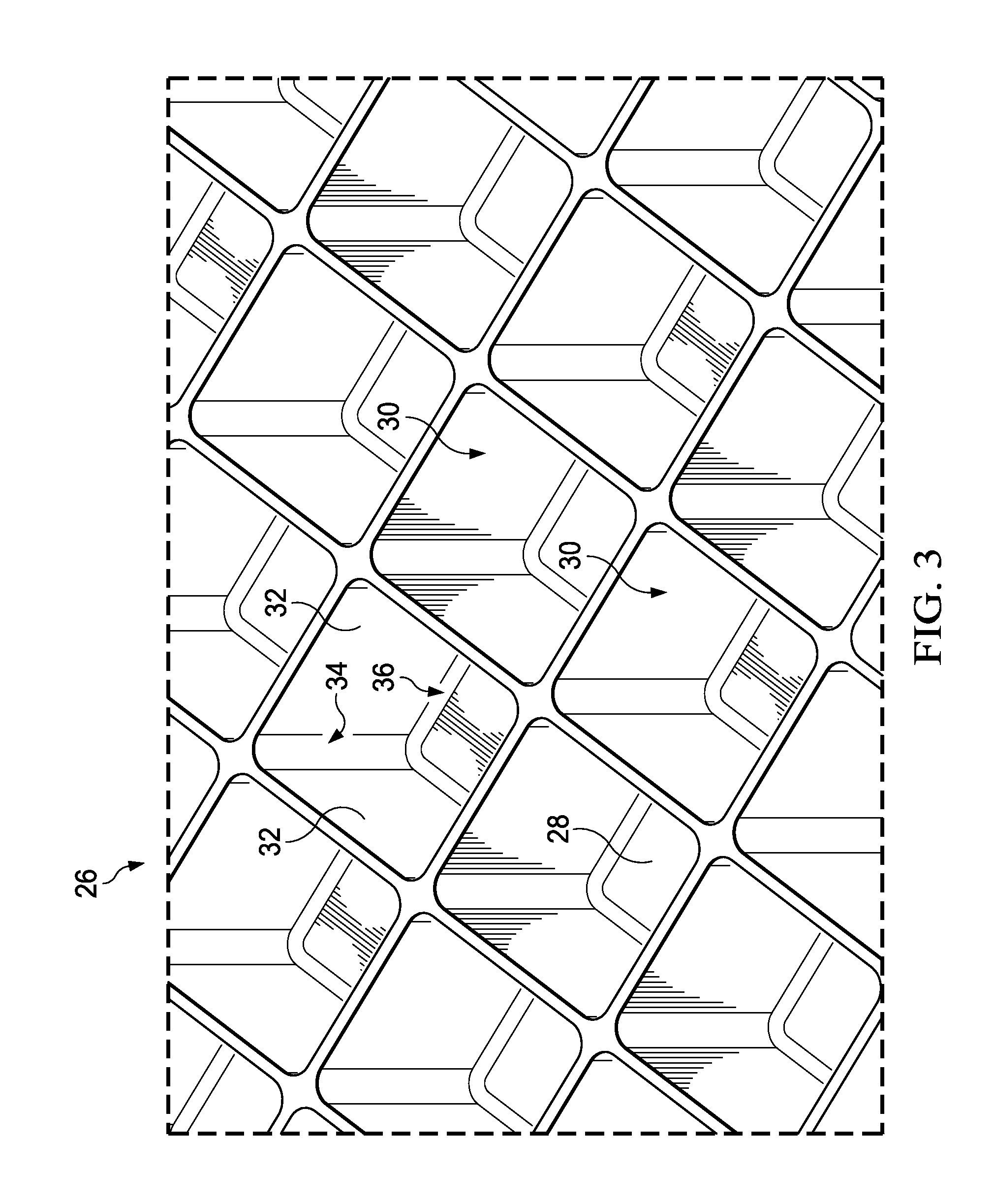
[0029]The disclosed embodiments may be employed to fabricate or rework composite structures that incorporate cell-based arrays, sometimes referred to herein as cell-based structural arrays. For example, referring to FIG. 1, a structural RF (radio frequency) aperture 20 used for communication may be integrated into the skin 22 of the aircraft fuselage 24. As shown in FIG. 2, the RF structural aperture 20 comprises an array 26 of cells 30 sandwiched between inner and outer facesheet 28, 29 to form a composite sandwich structure. Although the structural RF aperture 20 is shown as being located in the aircraft fuselage 24, it may be located in other areas of the aircraft, including but not limited to wings, cowls, stabilizers, doors, etc. Moreover, although an aircraft application is illustrated, the cell-based structural array may be incorporated into structures used in other applications, such as, for example and without limitation, land or sea vehicles satellites, etc.

[0030]Referring...


PUM

PropertyMeasurementUnit
structureaaaaaaaaaa
thermally conductiveaaaaaaaaaa
thermal conductivityaaaaaaaaaa

Abstract

Cells of a composite cell array are cured by placing tool blocks in the cells and inserting thermally conductive elements in each of the tool blocks. The thermally conductive elements are convectively heated by a flow of hot air. The heated conductive elements conduct heat to the tooling blocks, which then conduct heat to the cells to cure the composite and adhesive.

Description

BACKGROUND INFORMATION[0001]1. Field[0002]The present disclosure generally relates to manufacturing and reworking of adhesively bonded cell-based arrays, and deals more particularly with a method and apparatus curing the adhesive that bonds the cells and skin panels together.[0003]2. Background[0004]Cell-based structural arrays may be used to provide composite structures with strength and rigidity, and / or to form functional features such as a structural RF (radio frequency) aperture used for transmission and / or reception of RF signals. In one application, a cell-based structural array is bonded between inner and outer facesheets to form a sandwich structure. The cell-based structural array comprises individual hollow cells formed by cell walls that are adhesively joined together along bondlines. After the adhesive is applied, a bank of tooling blocks is inserted into the cells of the array, and the array along with the tooling blocks are placed in an oven or an autoclave for thermal...

Claims


Application Information

Patent Timeline
Patent Type & Authority Applications(United States)
IPC IPC(8): B32B37/06
CPCB32B37/06B29L2031/60B29D24/005B29C35/02H01Q21/0087B29C2035/046H01Q1/286Y10T156/10B29C35/0266
Inventor HAFENRICHTER, JOSEPH LAWRENCEMARSHALL, IV, JOSEPH A.
Owner THE BOEING CO
Why Eureka
Try Eureka