Drainage system for cerebrospinal fluid

a cerebrospinal fluid and drainage system technology, applied in the direction of positive displacement liquid engines, machines/engines, diagnostic recording/measuring, etc., can solve the problems of complicated structure and inability to control volume, and achieve the effect of convenient operation

Active Publication Date: 2013-12-17
MOLLER MEDICAL
View PDF29 Cites 7 Cited by
  • Summary
  • Abstract
  • Description
  • Claims
  • Application Information

AI Technical Summary

Benefits of technology

[0009]The object of the invention is therefore to improve an initially mentioned drainage system to the effect that, with an easily operated structure, it reacts more precisely to pressure changes in the liquor line.
[0015]As already mentioned above, it is advantageous for the accuracy of the pressure measurement if it is performed intracorporeally by a pressure sensor arranged in the intracranial cavity being treated. If the pressure measurement takes place only outside the patient's body in a liquor line, the cerebrospinal fluid pressure can be measured all the more precisely, the closer the pressure sensor is arranged to the skull opening. The accuracy of the measurement of the cerebrospinal fluid pressure is further improved if the pressure sensor is located as far as possible at the same height as the geometric center of the cranial cavity. According to a further advantageous embodiment of the present invention the pressure sensor in the liquor feed line is therefore equipped with fastening means which enable arrangement of the pressure sensor in the patient's head region. The pressure sensor may, for example, be fastened via a headband close to the skull hole or arranged on the patient's ear via an ear bracket or a clip. A further possibility for fastening a pressure sensor in the patient's head region is the use of clipped-on ECG adhesive pads at the desired measuring position on the temple or behind the patient's ear or an ECG adhesive electrode near the ear. It can be seen as a further advantage that the adhered or clipped-on sensor cannot slip and no malfunctions in the blood supply to the skin are caused by clamping or the contact pressure of a rubber band.
[0017]According to a preferred embodiment of the present invention the liquor drainage system comprises input means, via which specific operating parameters, such as, e.g. preset pressure limit values of the liquor pressure or the cerebrospinal fluid pressure in the ventricle to be treated, can be input into the control electronics. In the control electronics electronic memory means can also be provided, in which, for example, specific operating cycles of the liquor drainage system can be stored or kept available. The liquor drainage system may further comprise operating elements, via which the operation of the pump can be directly controlled. This provides the possibility of also controlling the pump manually, for example to generate a higher pumping capacity on short-term to eliminate blockages.
[0019]A hose pump, which has the advantage that the pumped fluid inside the hose system does not come into contact with any foreign bodies, is preferably used as pump. For the pressure measurement a piezoresistive pressure sensor in a micromechanical embodiment is particularly suitable. These pressure sensors are small in design and highly sensitive with comparatively low production costs. During the pressure measurement the sensor generates an electric signal which is proportional to the pressure to be measured. Piezoresistive sensors typically contain a silicon chip as sensor element, on the front of which the ambient pressure acts directly. In the present application the pressure of the liquor is transmitted to the back of the chip via a silicon gel. The difference between the ambient pressure and the pressure of the liquor causes the membrane of the chip to arch and the thus arising mechanical stresses are converted into a change in the measurement resistance in the sensor element. Because of the configuration of piezoresistive pressure sensors as a measuring bridge, an output voltage signal is generated which is proportional to the feed voltage of the sensor in the manner of a ratiometric sensor and to the differential pressure.
[0021]By contrast with the liquor drainage arrangements known from the prior art, in which liquor discharges into a collecting container only by its own hydrostatic pressure, in the system according to the invention the liquor is pumped out in a targeted manner, the volume pumped out being regulated by pressure control. In this way it is possible to set freely the volumes of liquor and intracranial pressure values via which the pumping process is regulated. Additionally, generation of a pressure in the hose system below a defined lower limit is possible, in order, e.g. to check the ability to penetrate the hose system or to remove foreign bodies (e.g. blood coagulum) blocking the hose system. In this way purely volume-controlled liquor drainage, as required for continuous lumbar drainage, for example, can be carried out with the liquor drainage system according to the invention.
[0025]The data transmission from the liquor drainage system to an external evaluation unit is done via an interface, such as, e.g. a cable, infrared or radio connection or with the aid of a memory card / chip. The liquor drainage system according to the invention may be further equipped with an additional output for transmitting operating data, in particular the liquor pressure signal, to external display monitors and with a call button for the service personnel. In order to guarantee mains-independent operation (for example in the event of a power outtage), the liquor drainage system is preferably equipped with a store for electric energy or an accumulator which ensures mains-independent operation for at least a few hours and facilitates transport of the patient with the system.

Problems solved by technology

This results in the disadvantage that, with this known liquor drainage system the amount of liquor draining out is also determined by the difference in height between the ventricular catheter and the collecting container.
In addition, volume-controlled drainage is not possible with this known liquor drainage system.
The liquor drainage arrangements known to date have the disadvantage that they have a complicated structure and adaptation of the discharge amount to changed pressure circumstances in the liquor feed line have to be performed either by mechanical means or manually.

Method used


Image

  • Drainage system for cerebrospinal fluid
  • Drainage system for cerebrospinal fluid

Examples


Embodiment Construction

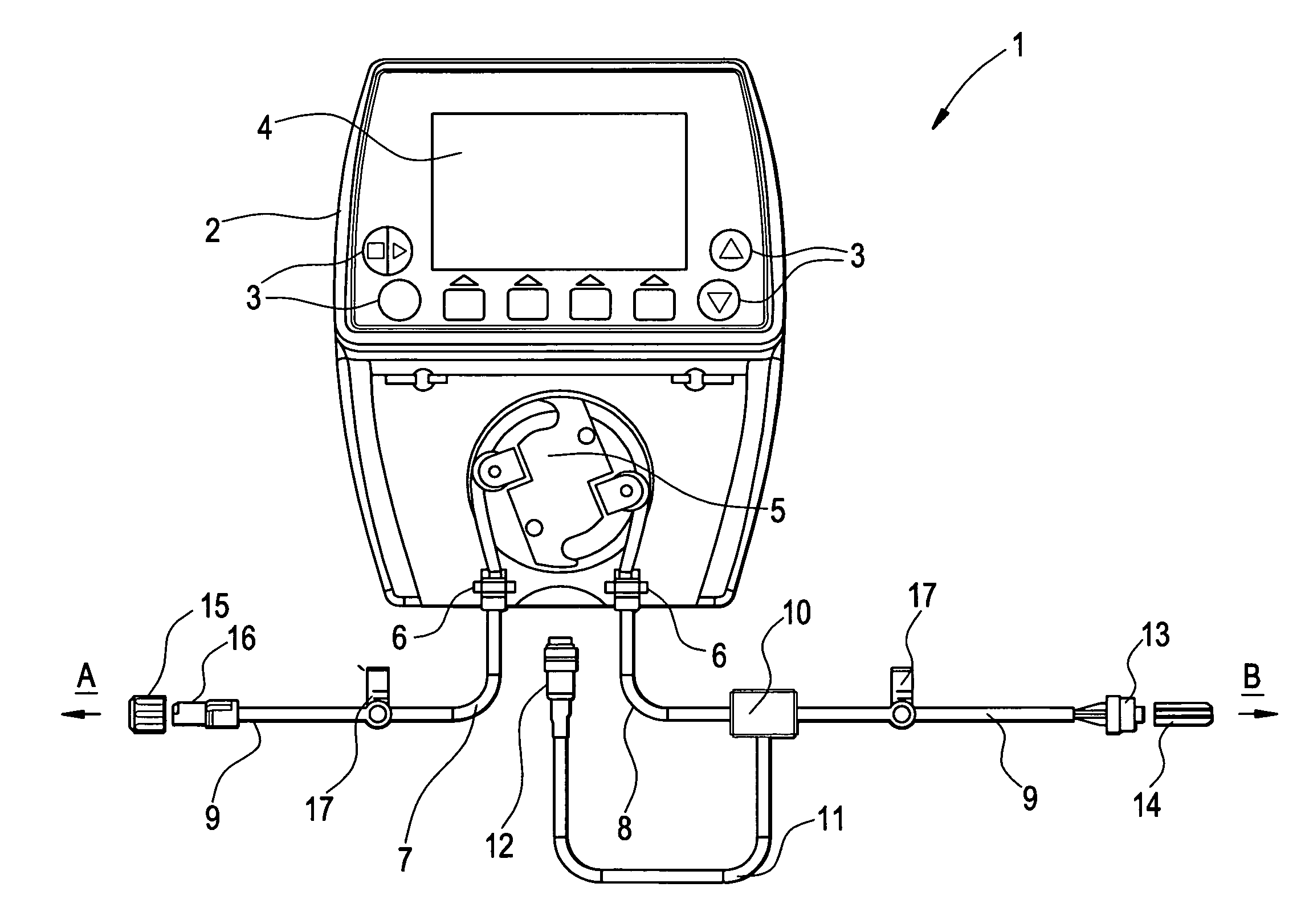
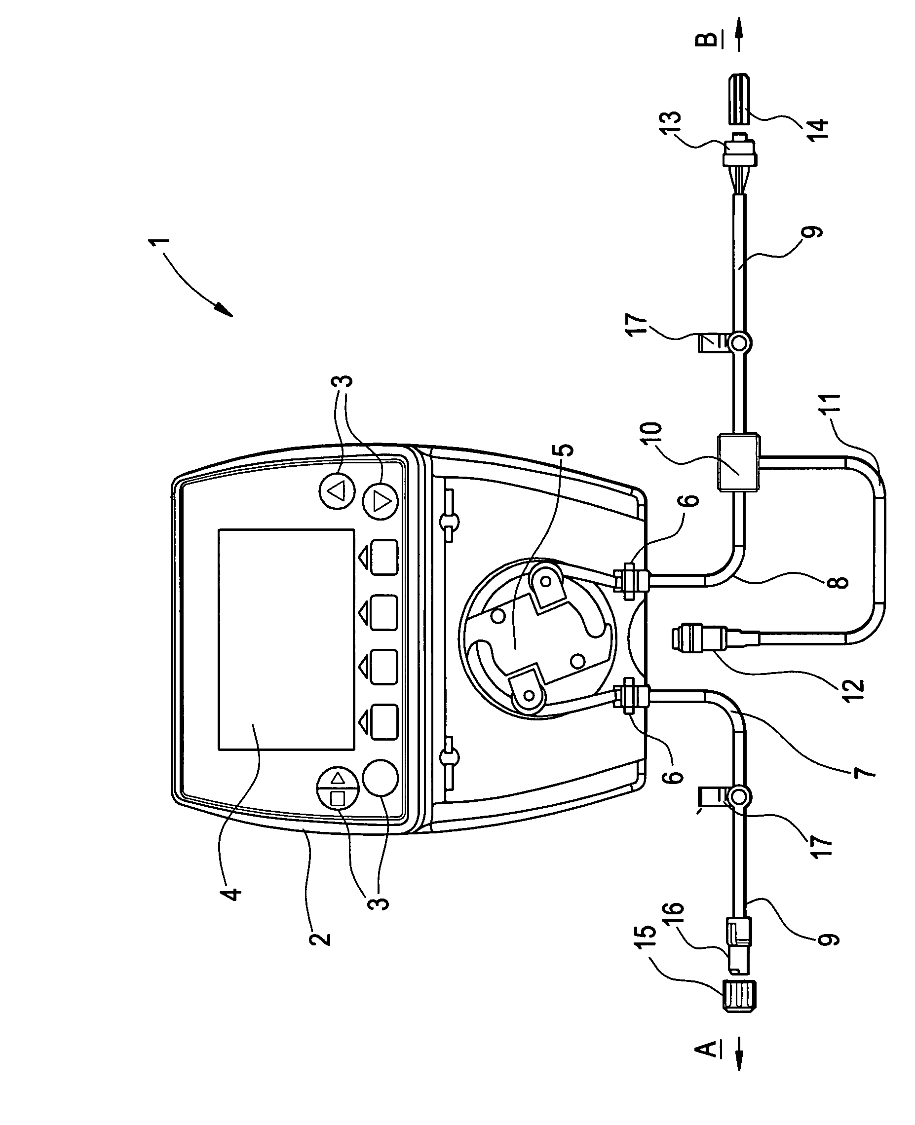
[0028]The embodiment of the liquor drainage system 1 shown in FIG. 1 comprises, according to the present invention, a main component 2 with a housing 2, in which an electronic control unit with electronic means for the above-described calculations is accommodated. Arranged on the housing 2 are input and operating elements 3, via which operating parameters required for the operation of the liquor drainage system 1 or a desired operating mode of the liquor drainage system 1 can be manually input. All the input operating parameters and / or current operating measured values and operating modes of the liquor drainage system 1 can be displayed via a display 4.

[0029]The main component 2 of the liquor drainage system 1 further comprises a hose pump 5 with connectors 6 for hose connections 9 of a hose system. The hose connections 9 connected to the hose pump 5 are on the one hand a liquor feed line (brain catheter) 8 between the hose pump 5 and the patient and on the other hand a hose connect...


PUM


Abstract

The object of providing a cerebrospinal fluid drainage system 1 which reacts precisely to changes in pressure in the cerebrospinal fluid, with ease of operation, is achieved by the present invention in that a pump 5 is used for draining the cerebrospinal fluid (liquor), wherein operating measured values supplied by sensors act as controlled variable for the operation of the pump. The pressure in the liquor line currently measured by a pressure sensor 10, the liquor pressure in the intracranial cavity being treated, measured intracorporeally by a pressure sensor, and / or the volume of liquor already pumped out, as operating measured value, can, for example, serve as the basis for operational control of the pump of the liquor drainage system. The liquor drainage system according to the invention has the advantage that the liquor is drained not only simply on the basis of the excess pressure in the intracranial cavity being treated, but is actively pumped out of the intracranial cavity in a controlled manner, in particular with constant measurement of the liquor pressure. In this way the pumping capacity can be regulated depending on requirement and the drainage pressure or the liquor pressure kept reliably within a specific pressure range.

Description

CROSS REFERENCE TO RELATED APPLICATIONS[0001]The present application is a Continuation of co-pending Application No. PCT / EP2006 / 002730, filed Mar. 24, 2006, which in turn, claims priority from European Application No. 05016789.9, filed Aug. 2, 2005. Applicants claim the benefits of 35 USC §120 as to the PCT application, and priority under 35 USC §119 as to the said European Application, and the entire disclosures of both applications are incorporated herein in their entireties.BACKGROUND OF THE INVENTION[0002]The invention relates in general to a device for the drainage of cerebrospinal fluid and in particular to a drainage system comprising a fluid (liquor) drainage line, a fluid pressure sensor, and a pump for pumpin out said fluid.[0003]In patients with hydrocephalus and / or increased intracranial pressure the surplus cerebrospinal fluid (liquor cerebrospinalis or in abbreviated form “liquor”) is either drained into any body cavity or into the blood by internal drainage devices or...

Claims


Application Information

Patent Timeline
Patent Type & Authority Patents(United States)
IPC IPC(8): A61F5/44
CPCA61M1/0023A61M27/006F04B43/1253A61B5/031A61M1/0031A61M2210/0693F04B2205/01A61M1/74A61M1/73
Inventor HOLPER, MANFREDTRAXLER, CHRISTOPHSCHROTER, WERNERMARTENS, DANIELAHOLPER, BERND M.
Owner MOLLER MEDICAL
Why Eureka
Try Eureka