Electric reversing control valve for oxygen production and control method

An electric reversing and control valve technology, applied in valve details, multi-port valves, valve devices, etc., can solve the problems of cumbersome control and complex structure, and achieve the effects of high transmission precision, simple and compact structure, and easy operation.

Inactive Publication Date: 2021-06-11
FEDERAL MEDICAL TREATMENT ENG CO LTD CHENGDU
View PDF8 Cites 0 Cited by
  • Summary
  • Abstract
  • Description
  • Claims
  • Application Information

AI Technical Summary

Problems solved by technology

In the prior art, multiple two-way control valves are often used in combination, and the PLC control

Method used


Image

  • Electric reversing control valve for oxygen production and control method
  • Electric reversing control valve for oxygen production and control method
  • Electric reversing control valve for oxygen production and control method

Examples


Embodiment 1

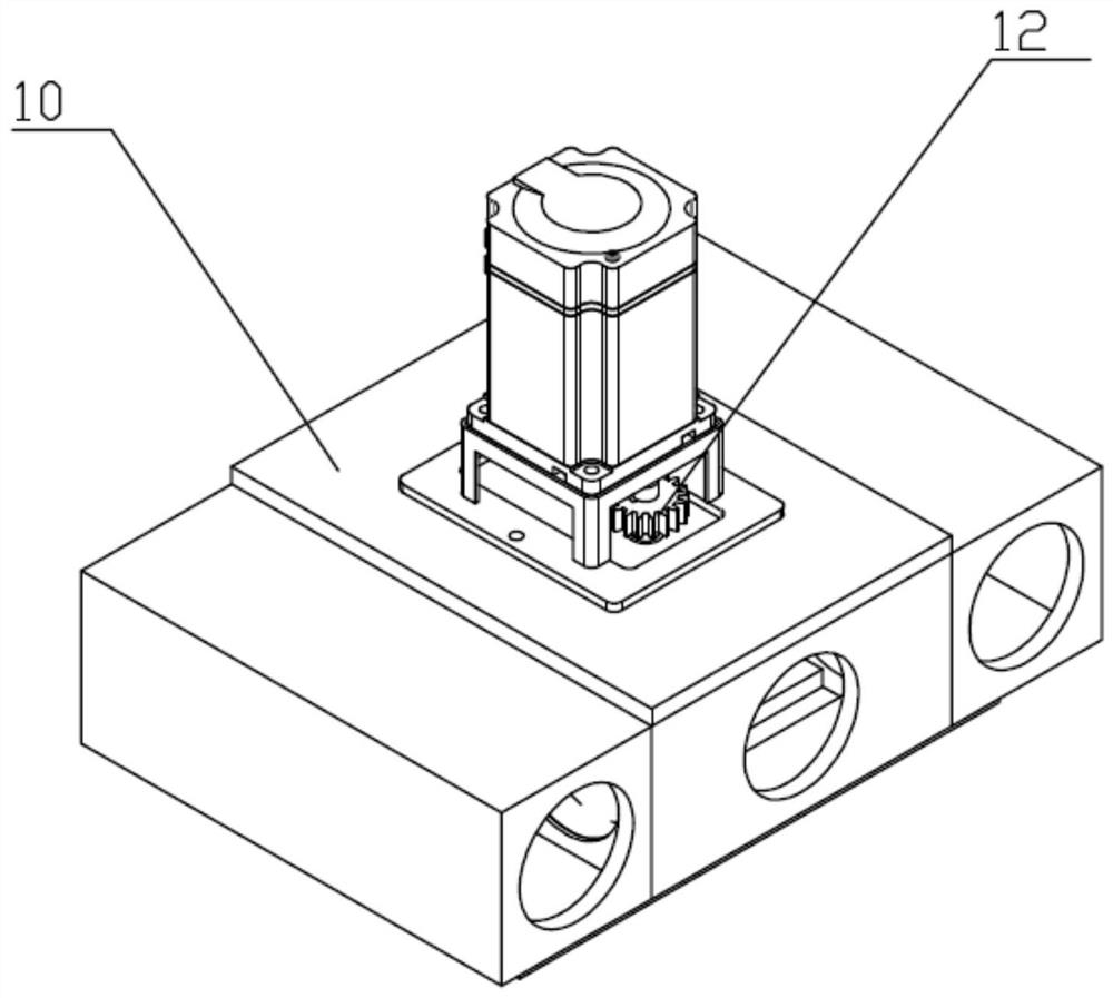
[0045] Such as Figure 1-Figure 6 As shown, the electric reversing control valve for oxygen production includes a valve body 10, a sealing mechanism 11 and a gear drive mechanism 12;

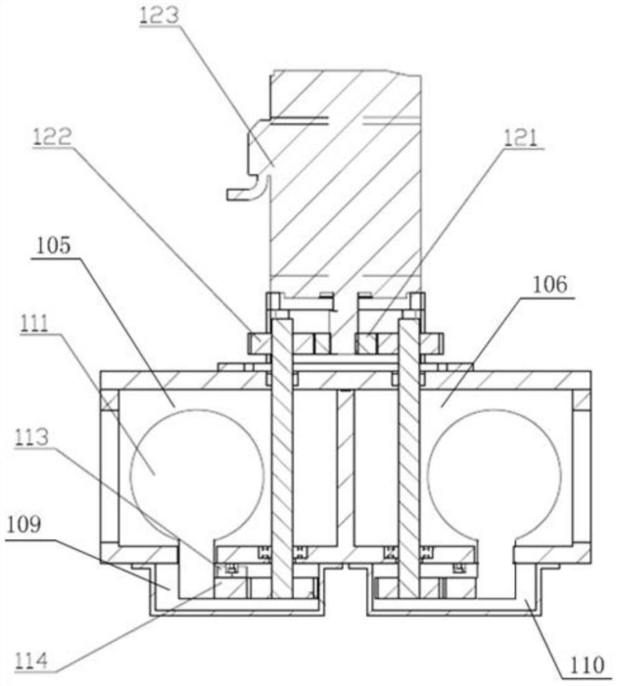
[0046]The valve body 10 is provided with a first public chamber 105, a second public chamber 106, a vacuum chamber 107 and a pressure chamber 108, and the vacuum chamber 107 is connected to the first public chamber 105 and the second public chamber 106 respectively through the first The first communication port and the second communication port communicate, and the pressure chamber 108 communicates with the first common chamber 105 and the second common chamber 106 through the third communication port and the fourth communication port respectively. A gas inlet and outlet 101 is provided, an adsorption tower connection port 102 is provided on the second public chamber 106, a fan inlet connection port 103 is provided on the vacuum chamber 107, and a fan outlet connection port is provided on the pr...

Embodiment 2

[0057] Such as Figure 1-Figure 6 Shown, this embodiment is based on embodiment 1,

[0058] In this embodiment, the first common cavity 105 and the second common cavity 106 are arranged symmetrically, and the vacuum cavity 107 and the pressure cavity 108 are arranged in parallel between the first common cavity 105 and the second common cavity 106, so The two ends of the vacuum chamber 107 communicate with the first public chamber 105 and the second public chamber 106 respectively through the first communication port and the second communication port, and the two ends of the pressure chamber 108 communicate with each other through the third communication port and the fourth communication port respectively. The port communicates with the first common chamber 105 and the second common chamber 106; the bottoms of the vacuum chamber 107 and the pressure chamber 108 are respectively provided with a first installation chamber 109 and a second installation chamber 110, and the first i...

Embodiment 3

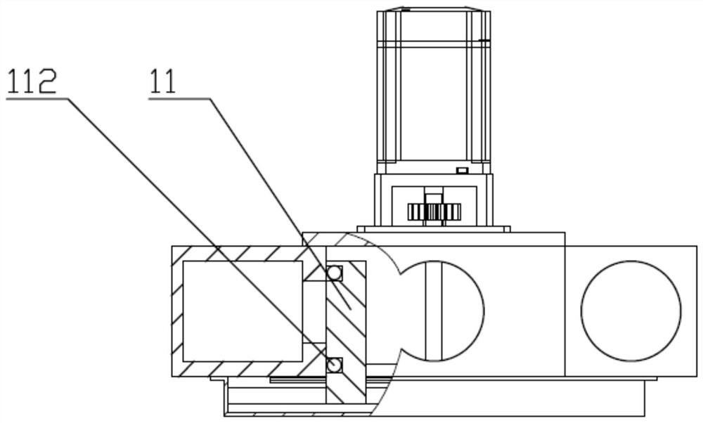
[0061] Such as Figure 1-Figure 6 As shown, this embodiment is based on Embodiment 1 or Embodiment 2, a seal ring 112 is provided on the side wall of the seal seat 111; a position detection sensor 115 is installed on the seal seat 111, and the position detection sensor 115 is connected to the A controller for driving the gear drive mechanism 12 is electrically connected.


PUM


Abstract

The invention discloses an electric reversing control valve for oxygen production and a control method. The electric reversing control valve for oxygen production comprises a valve seat, a sealing mechanism and a gear driving mechanism. The valve seat is divided into four sealing cavities including two public cavities, a vacuum cavity and a pressure cavity. The sealing mechanism is composed of a guide rail, a rack, a sealing seat and a sealing ring. The gear driving mechanism is composed of a driving wheel and two driven wheel assemblies, and the driving wheel is connected with a driving motor through a key. The driven wheel assemblies of the gear driving mechanism are driven by the driving wheel to rotate in the opposite directions, so that the rack of the sealing mechanism is driven to linearly move in the opposite directions. And the sealing seat of the sealing mechanism is connected with the rack and does linear motion in different directions along with the rack, so that the pressure cavity/vacuum cavity is communicated with the different public cavities, the switching of the working states of the control valve is realized, and the vacuum and pressure can be exchanged and output.

Description

technical field [0001] The invention relates to the technical field of oxygen production equipment, in particular to an electric reversing control valve for oxygen production and a control method. Background technique [0002] Molecular sieve oxygen production refers to the separation and production of oxygen from air at room temperature by using the adsorption characteristics of molecular sieves. In this process, it is usually necessary to alternately send air to the adsorption tower and extract vacuum, which requires a control valve to realize the conversion operation. In the prior art, a plurality of two-way control valves are often used in combination, and PLC control programs are used to control the valve action. The structure is complex and the control is cumbersome. Contents of the invention [0003] The object of the present invention is to provide an electric reversing control valve for oxygen production, which not only can realize the reversing quickly and smooth...

Claims


Application Information

Patent Timeline
IPC IPC(8): F16K11/065F16K31/04F16K31/54F16K37/00F16K27/04
CPCF16K11/0655F16K31/04F16K31/54F16K37/00F16K27/044
Inventor 龙兴华谢邦庆修京华
Owner FEDERAL MEDICAL TREATMENT ENG CO LTD CHENGDU
Why Eureka
Try Eureka