Manufacture of a portion of a metal part using the MIG method with pulsed current and wire

Active Publication Date: 2013-12-24
SN DETUDE & DE CONSTR DE MOTEURS DAVIATION S N E C M A
View PDF13 Cites 5 Cited by
  • Summary
  • Abstract
  • Description
  • Claims
  • Application Information

AI Technical Summary

Benefits of technology

[0006]It is an object of the invention to provide a technique for the manufacture or refurbishment of parts, or portions of parts, allowing large application of material by the formation of beads with a large cross section. While the manual TIG

Problems solved by technology

The major drawback of these methods is the associated production cost,

Method used


Image

  • Manufacture of a portion of a metal part using the MIG method with pulsed current and wire
  • Manufacture of a portion of a metal part using the MIG method with pulsed current and wire
  • Manufacture of a portion of a metal part using the MIG method with pulsed current and wire

Examples


Embodiment Construction

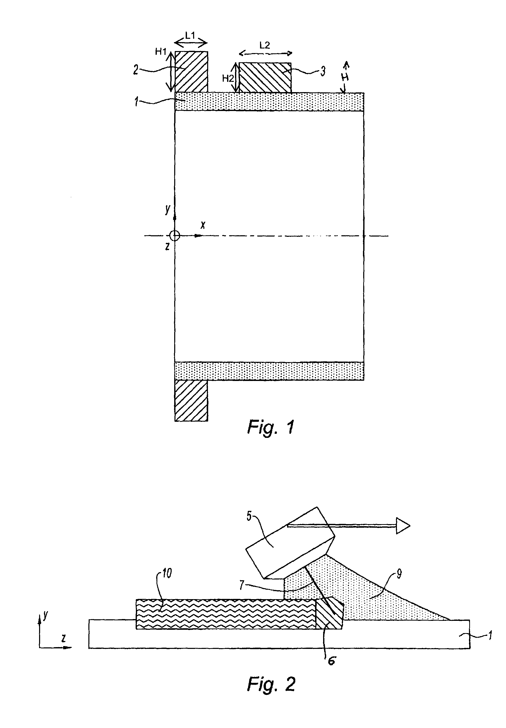
[0022]FIG. 1 represents a base part 1 of cylindrical shape and with a thickness at least equal to 3 mm, on which a flange 2 or alternatively a boss 3 is intended to be produced. The flange 2 is in the form of an annular portion, here on the end of the cylindrical part; it is produced over the entire circumference of the base part 1 with a determined height H1 and width L1.

[0023]The materials relevant to the method of the invention are stainless steels such as the one with the formula X5CrNiCul7.4 or W11CrNiMoV12, alloys based on nickel such as the one with the formula NiCr19Fe19Nb5Mo3 or based on cobalt such as the one with the formula CoCrNi22W, and titanium alloys such as the one with the formula TiAl6V.

[0024]The boss 3 is produced on a portion of the surface of the metal part. Its height H2 and its width L2 are also determined.

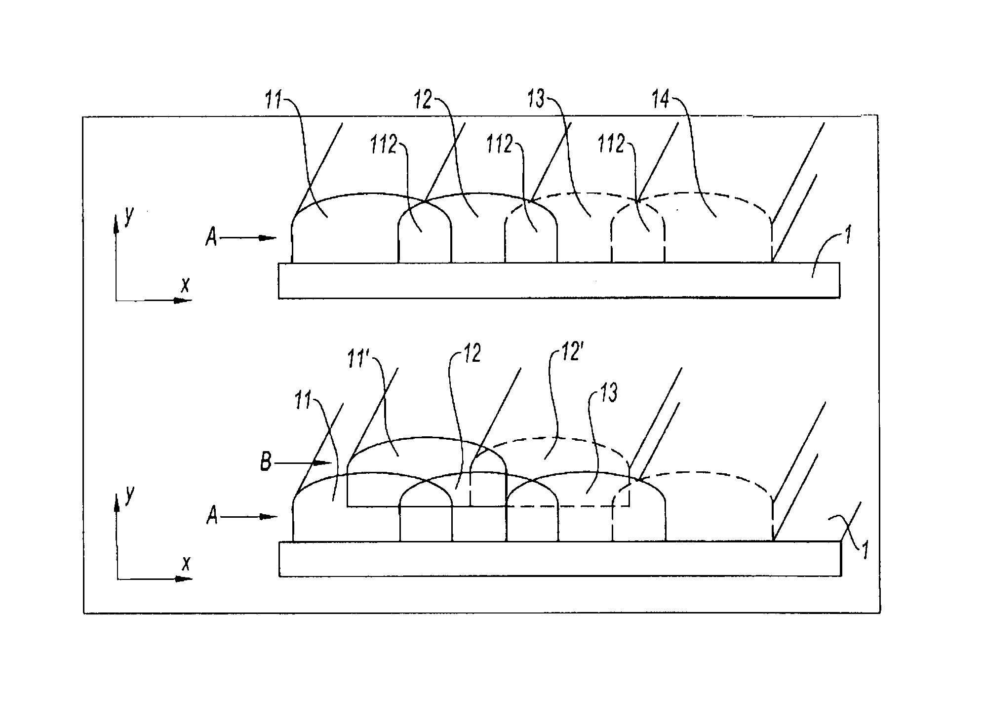
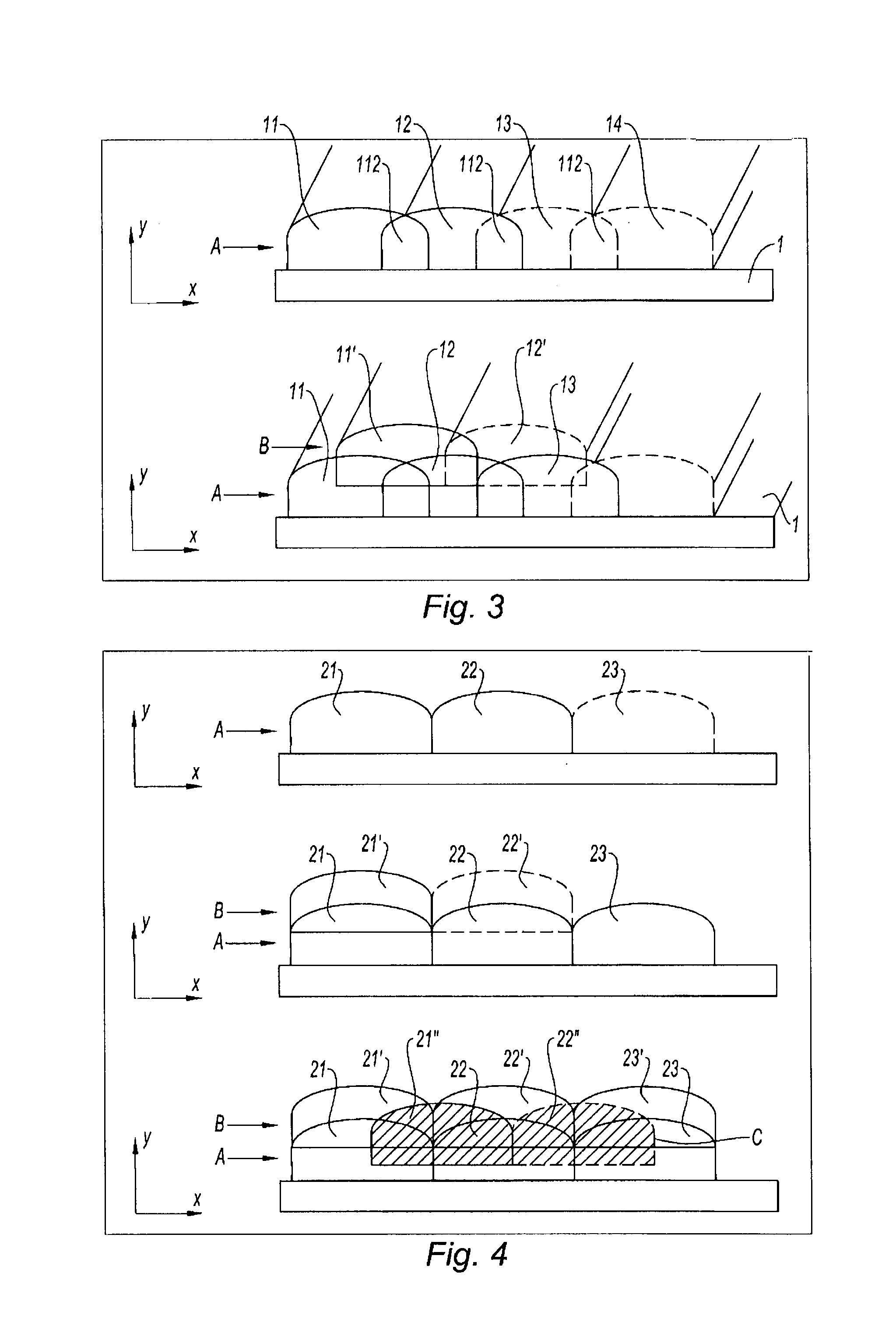
[0025]In order to manufacture the flange or the boss, one of the strategies developed in the manufacturing method of FIG. 3 or FIG. 4 may be used.

[0026]FIG...


PUM

PropertyMeasurementUnit
Thicknessaaaaaaaaaa

Abstract

A method for manufacturing at least a portion of a metal part of a turbine engine having a width. The portion of the metal part is manufactured by metal disposition using a MIG welding apparatus including a pulsed current generator and a pulsed deposition-wire flow, and used for varying the current and flow, the manufacture being carried out in the form of metal beads in several consecutive layers.

Description

BACKGROUND OF THE INVENTION[0001]1. Field of the Invention[0002]The invention relates to the manufacture and refilling of metal parts of a turbine engine. More particularly, the invention relates to the reaction of a discontinuous volume, in particular a flange or a boss.[0003]2. Description of the Related Art[0004]The creation of a discontinuous volume is currently achieved by conventional methods such as forging, casting or the welding of two parts. The major drawback of these methods is the associated production cost, in particular for small batches or for parts with a complex geometry.[0005]Welding of the TIG type (Tungsten Inert Gas) is a method of arc welding with a nonconsumable electrode in a gas atmosphere. This technique is used with a filler metal for manufacturing or refilling parts such as the blades of a turbine engine. The neutral gas, generally based on argon or helium, isolates the molten metal, the hot zones and the tungsten electrode from the air, thus avoiding an...

Claims


Application Information

Patent Timeline
IPC IPC(8): B21K25/00
CPCB23K9/048B23K9/09Y10T29/4932Y10T29/27Y10T29/49229B23K2201/001B23K2101/001
Inventor FLESCH, THIERRY JEAN EMILEMOTTIN, JEAN-BAPTISTE
Owner SN DETUDE & DE CONSTR DE MOTEURS DAVIATION S N E C M A
Why Eureka
Try Eureka