

Reusable thin film particle sensor
a technology of thin film particles and sensors, applied in the direction of porous material analysis, laboratory glassware, instruments, etc., can solve the problems of inconvenient use, high equipment costs, and inconvenient us
- Summary
- Abstract
- Description
- Claims
- Application Information
AI Technical Summary
Benefits of technology
Problems solved by technology
Method used
Image

Examples
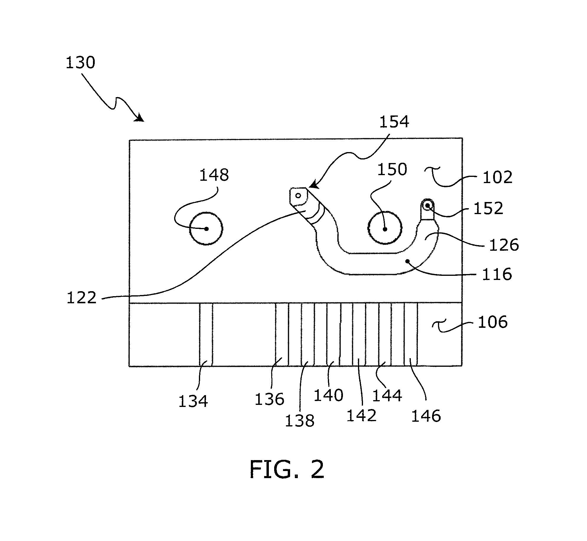
embodiment 130
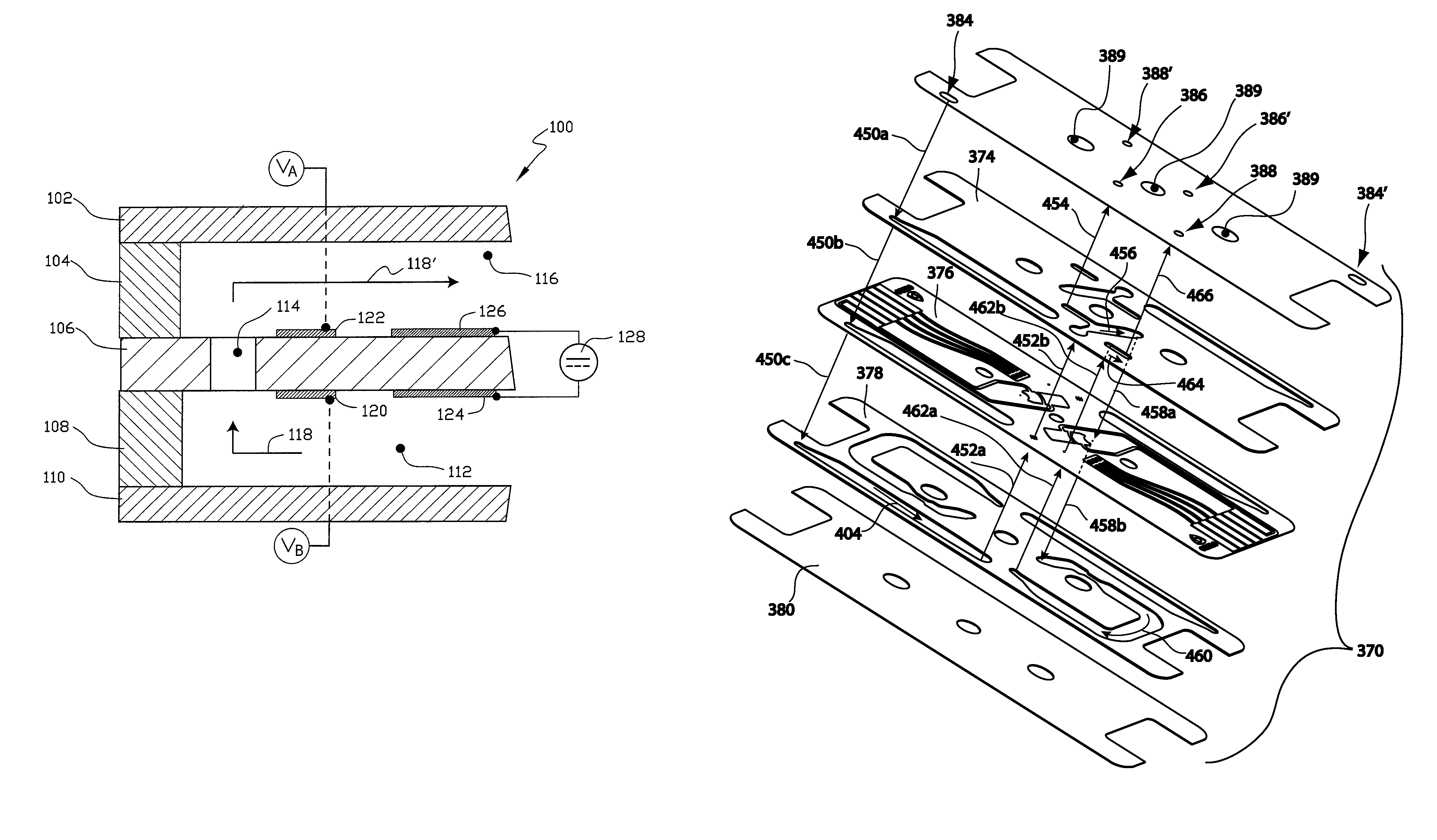
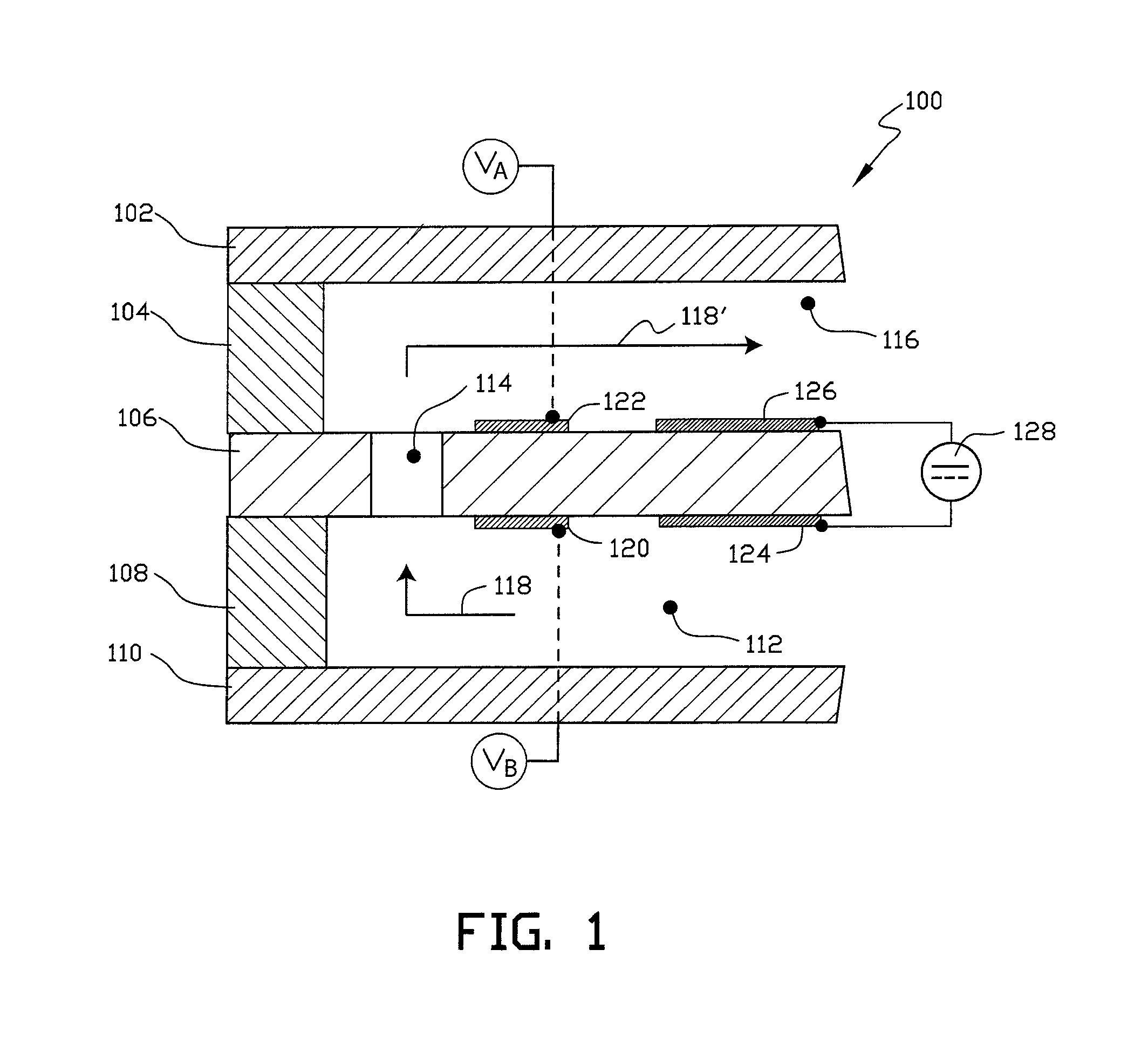
[0082]An electrical property at an electrode may be monitored to determine arrival of fluid at that electrode. For example, the impedance measured at an electrode undergoes a significant change in value as the wave-front, or the leading edge, an electrolyte fluid passes over the electrode. In one currently preferred use of the sensor component 130 (see FIG. 4), a stimulus electric signal (such as a 1 kHz square wave) is applied to electrode 164. A sudden change in the impedance values measured at electrodes 166 and 168 indicates the successive arrivals of the wave-front of the sample fluid at each respective electrode. In the illustrated embodiment 130, first verification of fluid at electrode 166 ensures that sample fluid is in place for interrogation, and a test run can begin. Feedback from electrode 166 may therefore serve as a first trigger to begin interrogation of the fluid sample.
[0083]A change in impedance at electrode 168 indicates the wave-front has reached that electrode ...
embodiment 280
[0111]A schematic illustrating a generalized operable arrangement of structure employed in embodiments structured according to certain principles of the invention and enabling optically-based interrogation is indicated generally at 280 in FIG. 20. As illustrated, embodiment 280 includes an opaque member, generally indicated at 282, disposed between a radiation source 284 and a radiation detector 286. At least one orifice 288 is disposed in opaque member 282 to provide a flow path between a first side, generally indicated at 290, and a second side, generally indicated at 292. Orifice 288 may be characterized as having a through-axis 294 extending between the first and second sides 290 and 292 of opaque member 282, respectively.
[0112]Both of the thickness, T1, of an opaque member and characteristic size, D1, of an orifice 288 are typically sized in agreement with a size of a particle of interest to promote single-file travel of the particle through the opaque member, and to have only ...
PUM
| Property | Measurement | Unit |
|---|---|---|
| thickness | aaaaa | aaaaa |
| thickness | aaaaa | aaaaa |
| thickness | aaaaa | aaaaa |
Abstract
Description
Claims
Application Information