
System and method of controlling power delivery to a surgical instrument

a surgical instrument and power supply technology, applied in the field of electrical surgical instruments and/or thermal surgical instruments, can solve the problems of surgeons being required to use electrosurgical devices, heat management within the device itself, and adverse outcomes for patients, and achieve the effect of preventing the tip from sticking to the tissu

Active Publication Date: 2013-12-31
DOMAIN SURGICAL
View PDF327 Cites 18 Cited by
  • Summary
  • Abstract
  • Description
  • Claims
  • Application Information

AI Technical Summary

Benefits of technology

The invention relates to a surgical instrument that can perform both electrosurgical and thermal surgical procedures. The instrument has a controlled power delivery system that uses an algorithm to adjust the power to the active part of the instrument based on the environment it is being used for. This prevents the instrument from overheating or exceeding the Curie point, resulting in better surgical outcomes. Additionally, the instrument has a removable thermal element, allowing for different thermal tips to be used with the handpiece. The power control algorithm also includes intermittent increases in power to prevent the instrument tip from sticking to the tissue being treated.

Problems solved by technology

If the temperature of the electrosurgical and / or thermal instrument is not properly controlled, then undesired results may occur which may lead to an adverse outcome for the patient.
Furthermore, a surgeon may be required to use an electrosurgical and / or thermal instrument for a prolonged period of time during a given procedure.
This can lead to problems both with heat management within the device itself as well as heat management of the heated surgical tip of the instrument.
For example, if heat transfer to a portion of the electro surgical and / or thermal instrument which is gripped by the surgeon is not properly controlled, the device may become too hot and the surgeon may not be able to handle the instrument for the time necessary to complete the procedure.
Additionally, if the active portion of the electrosurgical and / or thermal instrument, such as a thermal element, is overheated or exposed to excessive thermal stress, the thermal element may be damaged.

Method used


Image

  • System and method of controlling power delivery to a surgical instrument
  • System and method of controlling power delivery to a surgical instrument
  • System and method of controlling power delivery to a surgical instrument

Examples


Embodiment Construction

[0043]The invention and accompanying drawings will now be discussed in reference to the numerals provided therein so as to enable one skilled in the art to practice the present invention. The drawings and descriptions are exemplary of various aspects of the invention and are not intended to narrow the scope of the appended claims.

[0044]As used herein, the term “ferromagnetic,”“ferromagnet,” and “ferromagnetism” refers to substances such as iron, nickel, cobalt, etc. and various alloys that exhibit high magnetic permeability, a characteristic saturation point, and magnetic hysteresis.

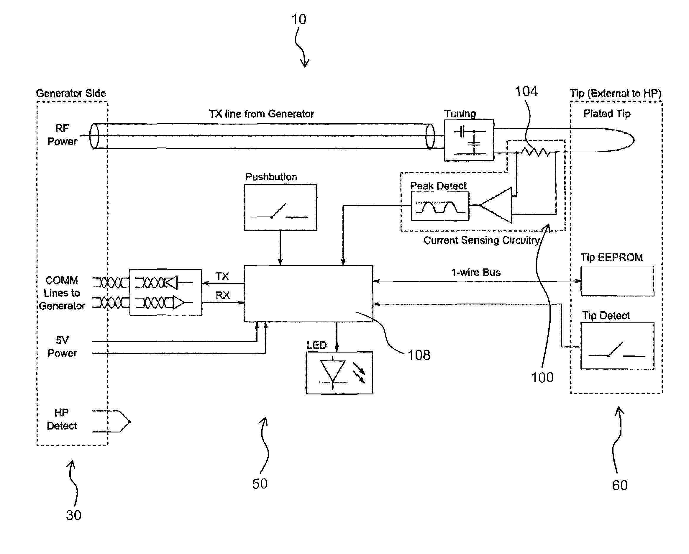
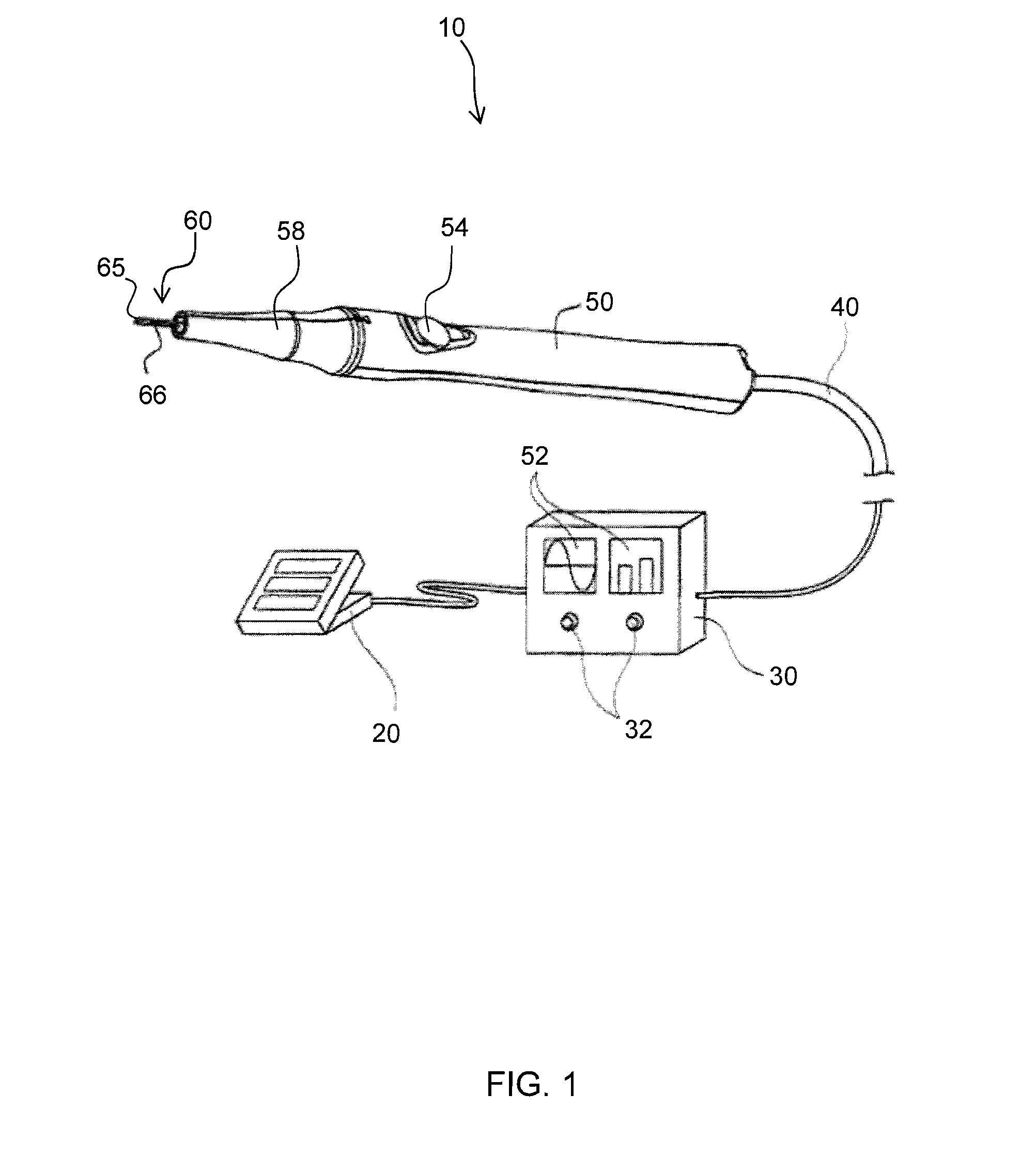
[0045]Turning now to FIGS. 1 through 3, FIG. 1 shows a perspective view of a thermal surgical instrument system, generally indicated at 10. As will be discussed in additional detail below, the thermal instrument system 10 may use a conductor associated with a ferromagnetic material to treat or destroy tissue (e.g. endothelial tissue welding, homeostasis, ablation, etc).

[0046]It will be appreciated that t...


PUM

PropertyMeasurementUnit
temperatureaaaaaaaaaa
poweraaaaaaaaaa
poweraaaaaaaaaa

Abstract

A thermal surgical instrument having a system to control the delivery of power from an energy source to active element located on a tip. The system for controlling delivery to the tip may include a control algorithm which uses one or more measurements, such as tip current, SWR, and rapid changes in reflected power, to manage power without affecting cutting efficacy, and in a manner that may be imperceptible by a surgeon. The system may utilize a state machine to determine the current environment in which the tip may be in. Power delivered to the tip may be selectively managed according to a fixed power index or a repeatedly executed power profile.

Description

THE FIELD OF THE INVENTION[0001]The present invention relates to electrosurgical and / or thermal surgical instruments. More specifically, the present invention relates to a system and method of controlling the delivery of power from an energy source to the instrument.BACKGROUND[0002]It is becoming more common to use electrosurgical and / or thermal devices during surgery because such devices may provide benefits over traditional medical devices. For example, electrosurgical and / or thermal devices may allow a surgeon to make precise incisions with limited blood loss. Because of their advantages, electrosurgical and / or thermal devices may be used in dermatological, gynecological, cardiac, plastic, ocular, spine, ENT, maxillofacial, orthopedic, urological, neurological and general surgical procedures as well as certain dental procedures, just to name a few.[0003]Surgery generally involves cutting, repairing and / or removing tissue or other materials. Electrosurgical and / or thermal instrume...

Claims


Application Information

Patent Timeline
Patent Type & Authority Patents(United States)
IPC IPC(8): A61B18/04A61B7/00
CPCA61B18/1445A61B18/1477A61B18/10A61B2018/141A61M25/00A61B2018/00577A61B2018/00875A61B2018/00827A61B18/082A61B2018/00107A61B2018/1412A61B2018/00642A61B2018/00791A61B2018/00607A61B18/04A61B18/1233A61B2018/00714A61B2018/0072A61B2018/00922A61B2018/00702A61B2018/00988
Inventor DENIS, SCOTTMANWARING, PRESTONEGGERS, PHILMANWARING, KIM
Owner DOMAIN SURGICAL
Learn More