
Downhole assembly

a technology of drill string and assembly, which is applied in the direction of drilling accessories, drilling machines and methods, earth-moving drilling and mining, etc., can solve the problems of torsional vibration of drill string, failure of drill string, and added expense of remedial work, and achieves simplified hydraulic circuitry

Inactive Publication Date: 2014-01-07
MCLOUGHLIN STEPHEN JOHN +1
View PDF22 Cites 25 Cited by
  • Summary
  • Abstract
  • Description
  • Claims
  • Application Information

AI Technical Summary

Benefits of technology

[0077]In an embodiment, the invention comprises a system and apparatus and method of controlling and adjusting the attitude of drill-collars with respect to the drill-bit in the rotary drilling process, the advantage of which, via means of a ball-joint torque transfer mechanism, allows for relative lateral motion therebetween. Advantageously, the attitude control mechanism provides for reduced lateral vibration which substantially diminishes bit radial force and mass imbalances, resulting in an improvement to the rate-of-penetration. The attitude adjustment is intrinsic to the device, system and apparatus.

Problems solved by technology

As a result of having these two major elements incorporated into the drillstring and adding bit and drill collar torsional resonance the drillstring undergoes harmonic oscillations which, at best, represent inefficiencies in the drilling process and at worst can cause drillstring failure with the added expense and unpredictability of remedial work.
Warren and Oster in “Improved ROP in Hard and Abrasive Formations” conclude that drill-collar torsional resonance in hard rock environments is responsible for PDC cutter damage and that reverse rotation of the drilling assembly is one of the more damaging elements of this particular drilling environment.
For example, variations in the torque applied to the drill string will result in a torsional vibration in the drill string.
As can be inferred, “stick-slip” is a chaotic issue.
When, however, the bit is “off-bottom” it is evident that stick-slip decreases.
Unfortunately having the bit off bottom also compromises the efficiency and economics of the drilling process.
. . probably due to unevenness of formation strength, random breakage or rock and amplification of these effects by mode coupling .
However, for the purposes of remedial action it is insufficient merely to measure quantities of shock and vibration.
Prior art in the domain of vibration measurement and control is plentiful, yet, to date, there has been little success in creating a panacea for stick-slip or success in diminishing drillstring harmonics and thereby deriving improvements to the drilling process.
Thus variations in bit generated torque will reflect in drillstring torque which feeds back into the rotary drive system: the system is complex, iterative and constantly changing.
In certain environments and circumstances, however, both approaches have achieved limited success.
These devices have some degree of effectiveness, but are constrained by having their own internal natural frequency, which, at some stage will compound the existing wellbore harmonic.
Additionally, shock subs are, largely, incompatible with directional drilling processes, directional wells and also relatively ineffective when dealing with high magnitude harmonic vibrations.
These devices also have inherent natural frequencies of their own which are not field tunable to provide damping capability Across wider ranges of harmonic vibration.
A recent study has shown that these equations, even when modified to account for fluid added mass and precessional forces, do not accurately predict critical rotating speeds and do not correspond well with field experience.”
Presently no generally accepted method exists to accurately predict critical rotary speeds.”
However, even slight hole enlargement reduces pre-well BHA Modeling effectiveness as it alters the natural frequency of the BHA.
The degree of hole enlargement is, additionally, unquantifiable until the well is in progress.
Research has shown that the main causes of premature bit and BHA damage in any one drilling scenario are, largely, confined to one or two major frequencies with single “sidebands”.
Unfortunately, not all of these inputs can be measured in the downhole environment.
Using these methods may reduce harmonic vibration, yet compromise rate of penetration as a result of the selection of sub-optimal drilling RPM ranges.
For example, extreme bit slip-stick torsional vibrations have been observed to cause BHA lateral instability which can in turn trigger whirl as a result of increased BHA / Wellbore interaction.
Conversely, BHA whirl can induce lateral bit instability”
Additionally, the stabilization means conveys potentially destructive energy from the drilling assembly to the borehole wall.
Given the frequency of harmonic vibrations associated with the drilling process and the requirement for timely corrective action, hydraulic system response times may prove to be inadequate for active damping control mechanism purposes.
Despite the use of mechanical damping means with various natural frequencies in combination with MR damping mechanisms, the experiments which were carried out and reported in Raymond showed that some spring configurations were less beneficial than others.
The inventors believe that the partial successes of prior art and the body of information accumulated to date indicate that it is insufficient to obtain sensor data from a single source of harmonics and that an integrated closed loop, adaptive approach is required.
Notwithstanding sensor measurements made within the instant device, without information pertaining to wider environmental conditions and at a minimum surface RPM, the downhole device has insufficient information to be able to determine the appropriate frequency of corrective actions.
It may be noted that all downlink prior art protocols, unless using customized, hard-wired drillpipe, for example, such as those proposed in Hall (U.S. Pat. No. 6,670,880) “DOWNHOLE DATA TRANSMISSION SYSTEM and Hall (U.S. Pat. No. 6,392,317) “ANNULAR WIRE HARNESS FOR USE IN DRILL PIPE, in some way compromise the integrity of drilling operations.

Method used


Image

  • Downhole assembly
  • Downhole assembly
  • Downhole assembly

Examples


Embodiment Construction

Including a Functional Explanation

[0098]The device will first be discussed in general terms in order to explain embodiments of the invention. It will be described in several forms, all of which have similar objectives and which have varying degrees of technical complexity. Principally, this device differs from prior art in the field of downhole vibration damping in that it provides damping for rotational, longitudinal and lateral vibrations, it is responsive to information conveyed to it in real time from the surface of the Earth, that it is constructed with an inherently variable natural frequency and that, advantageously, it seeks to harvest energy from the downhole environment.

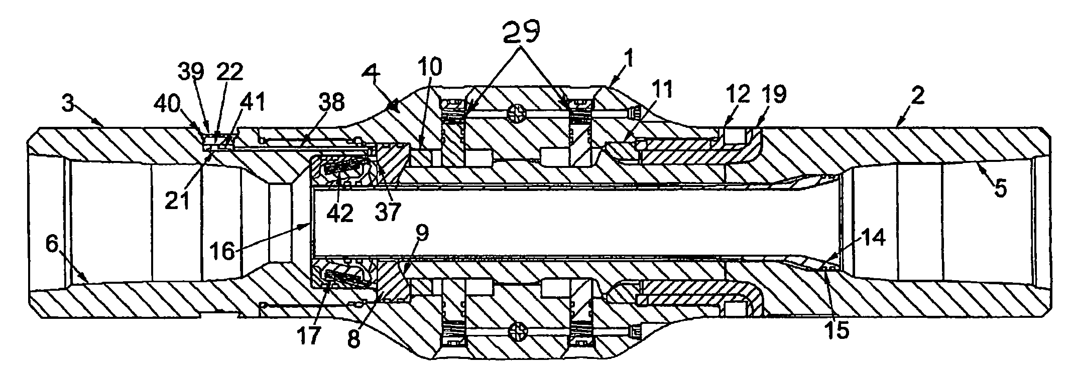
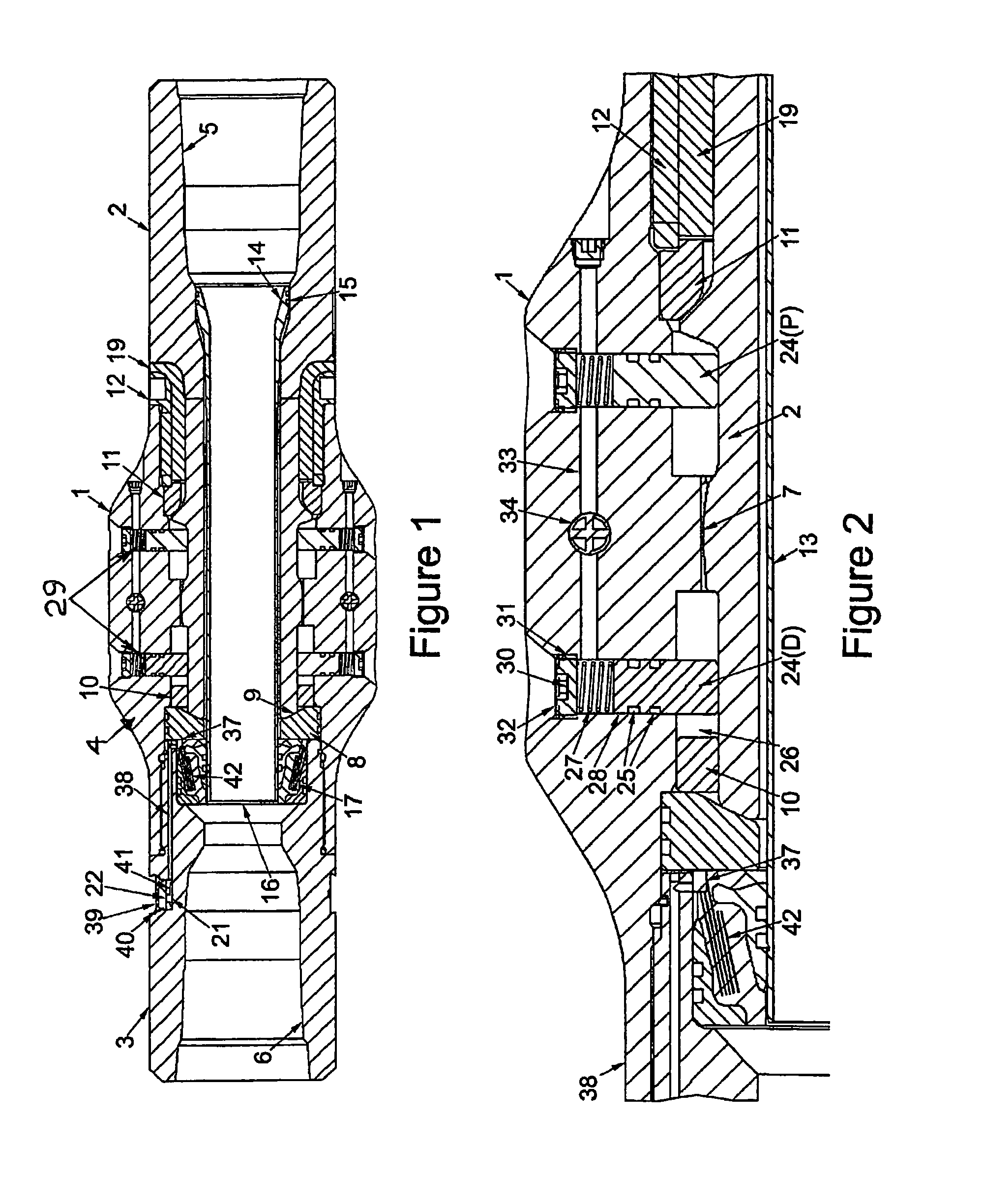
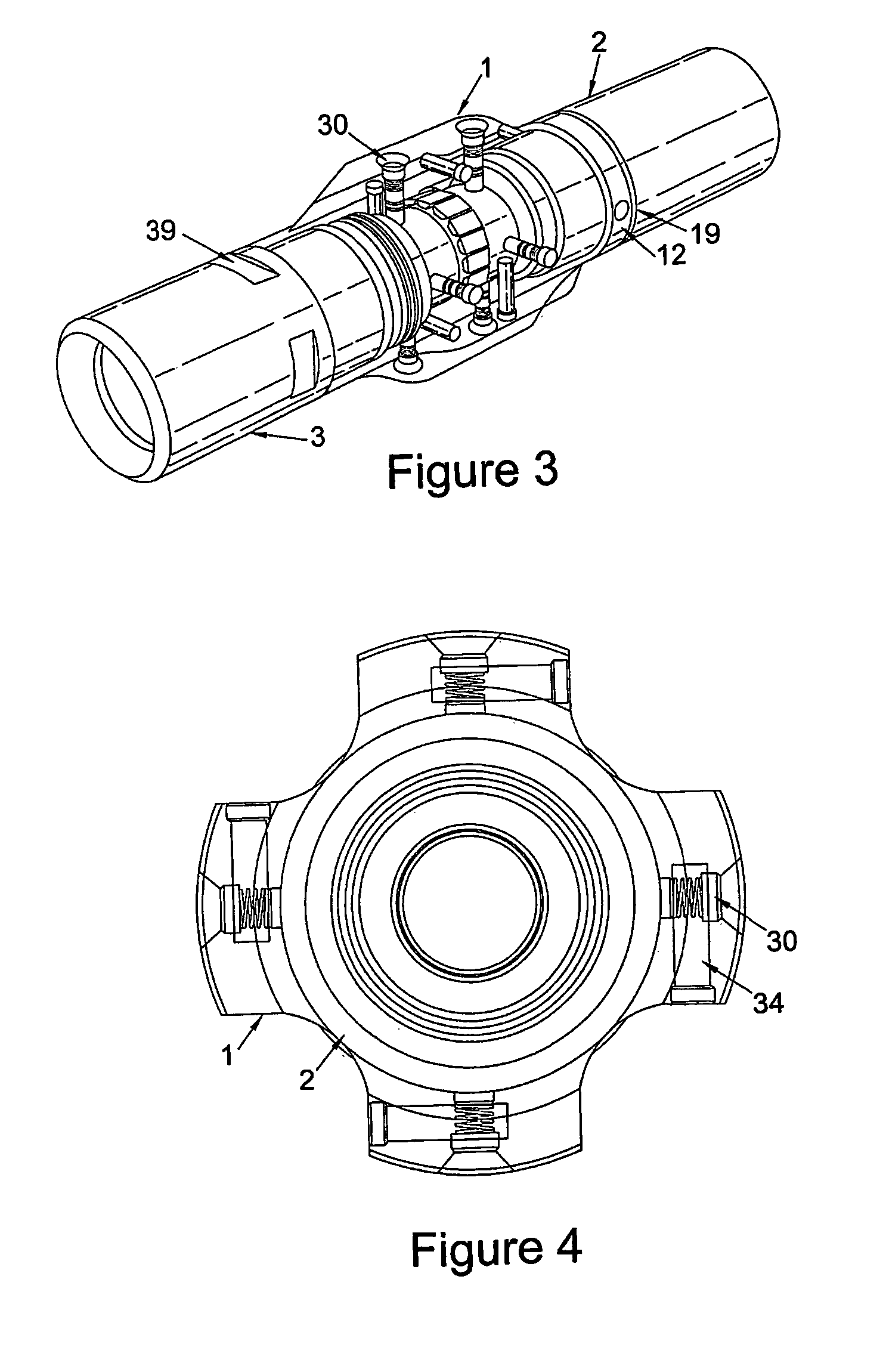
[0099]Referring to FIG. 1: The instant stabilized mechanism comprises a stabilizer sleeve element [1] which is radially co-located about a bi-partite internal mandrel sub-assembly [2], [3]. The stabilizer may be equipped with any of a variety of well understood stabilization means [4] which formats may incl...


PUM


Abstract

A downhole assembly for insertion into a borehole comprising an articulated mandrel, a passive and an active damping mechanism operating on said mandrel for exercising control over torsional stick-slip and further proposing an improvement over the prior art which diminishes lateral shock.

Description

[0001]This disclosure claims benefit of priority from U.S. Provisional Application U.S. 60 / 967,307 filed in the U.S. Patent and Trademark Office on 4 Sep. 2007.TECHNICAL FIELD OF THE INVENTION[0002]The present invention relates to the field of rotary drilling tools.BACKGROUND ART[0003]In the field of rotary drilling the drillstring, obeying Hooke's Law is perceived, to act as a spring. The lower component of the drillstring, however, reacts differently to the drillpipe section of the drillstring as it has a very high torsional stiffness combined with a high modulus of elasticity. As a result of having these two major elements incorporated into the drillstring and adding bit and drill collar torsional resonance the drillstring undergoes harmonic oscillations which, at best, represent inefficiencies in the drilling process and at worst can cause drillstring failure with the added expense and unpredictability of remedial work.[0004]Warren and Oster in “Improved ROP in Hard and Abrasive...

Claims


Application Information

Patent Timeline
Patent Type & Authority Patents(United States)
IPC IPC(8): E21B17/10
CPCE21B17/1078E21B17/10E21B17/1014E21B41/0085E21B17/07E21B17/05E21B17/073
Inventor MCLOUGHLIN, STEPHEN JOHNSWIETLIK, GEORGE
Owner MCLOUGHLIN STEPHEN JOHN
Learn More