In-vehicle power transmission device and driving system for vehicle

a technology of transmission device and driving system, which is applied in the direction of electric propulsion mounting, electric propulsion device mounting, transportation and packaging, etc., can solve the problems of hybrid vehicles facing difficulty in resuming difficulty in bringing a rotor, and inefficient energy use of the internal combustion engine, so as to facilitate the rotation of the driven wheel and eliminate the loss of electric energy.

Active Publication Date: 2014-01-07
NIPPON SOKEN +1
View PDF22 Cites 8 Cited by
  • Summary
  • Abstract
  • Description
  • Claims
  • Application Information

AI Technical Summary

Benefits of technology

[0019]It is another object of the invention to provide a power transmission apparatus for a vehicle designed to start an internal combustion engine effectively.
[0043]Specifically, the engine may be started by the torque outputted from the power split rotor, thus eliminating the need for a separate engine starter. Further, the transmission of power between the first and second rotors and the engine may be blocked and established selectively, thus minimizing the amount of energy consumed by the application of torque to the engine when being at a stop and enabling the transmission of torque between the first and second rotors and the engine as a function of differences in speed between the rotating shaft of the engine and the first and second rotors.

Problems solved by technology

The hybrid vehicles are typically controlled to stop the internal combustion engine in a low speed running range in view of the fact that the internal combustion engine is usually inefficient in energy use in the low speed running range.
The hybrid vehicles are facing a difficulty in how to restart the internal combustion engine during running of the vehicles.
For example, it is difficult to bring a rotor which is coupled with driven wheels of the vehicle and now rotating into mechanical connection with the crankshaft of the internal combustion engine which is at a stop.
The direct coupling of the rotating shaft of the electric motor to that of the internal combustion engine, as described above, will cause the torque load, as produced by the internal combustion engine, to be exerted on the electric motor, thus resulting in an increase in consumed amount of energy.
A problem is also encountered that when the internal combustion engine is started, the pulsation of torque occurring at the rotating shaft of the internal combustion engine may result in a decrease in driveability of the vehicle.
Further, the use of the planetary gear speed reducer leads to the problem that starting of the internal combustion engine when the rotational speed of the carrier is low will cause the internal combustion engine to be kept run at low speeds for a while.
This is against the intended purpose of the hybrid vehicles to run the internal combustion engine in a speed range in which the efficiency in energy use is high.

Method used


Image

  • In-vehicle power transmission device and driving system for vehicle
  • In-vehicle power transmission device and driving system for vehicle
  • In-vehicle power transmission device and driving system for vehicle

Examples


first embodiment

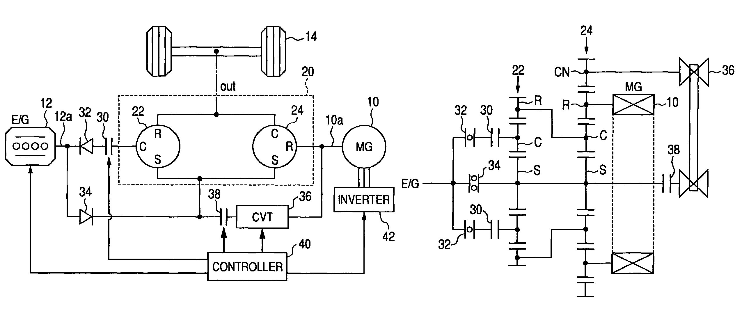
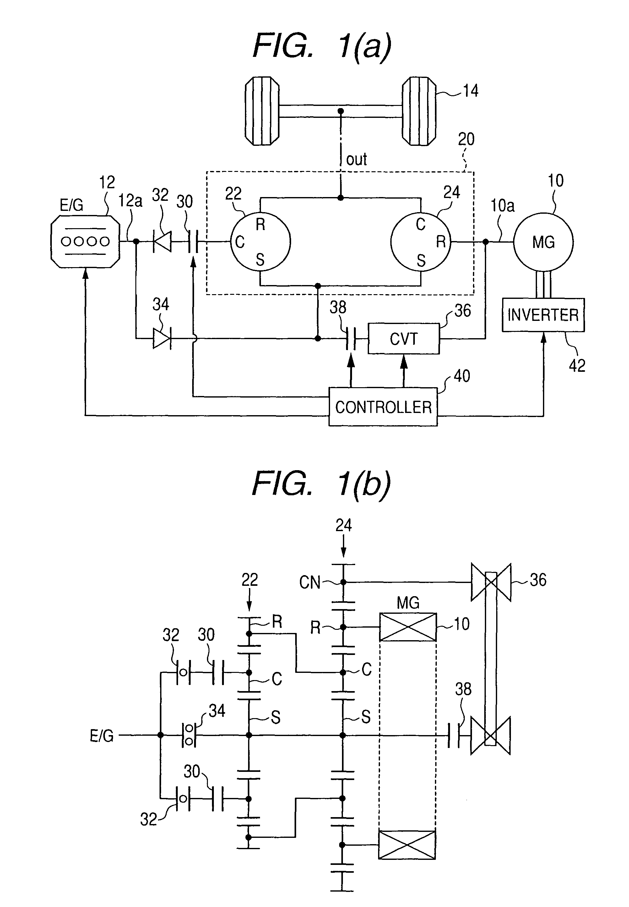
[0102]Referring to the drawings, wherein like reference numbers refer to like parts in several views, particularly to FIGS. 1(a) and 1(b), there is shown a hybrid system made up of an in-vehicle power transmission device and a driving system according to the invention. The in-vehicle power transmission device of this invention may alternatively be used with either an electric vehicle (EV) equipped only with an electric motor as a power source for running a road wheel or an automotive vehicle equipped only with an internal combustion engine as a power source for running a road wheel. The driving system is equipped with the in-vehicle power transmission device and a controller working to control an operation of the power transmission device. The driving system may also have installed therein a power source such as a motor-generator, an electric motor, or an internal combustion engine.

[0103]FIG. 1(a) illustrates the structure of the hybrid system. FIG. 1(b) is a skeleton view of power ...

second embodiment

[0139]FIG. 5 illustrates a hybrid system according to the invention. The same reference numbers as employed in FIG. 1 refer to the same parts, and explanation thereof in detail will be omitted here.

[0140]The hybrid system of this embodiment is designed to switch between the rotors of the power split device 20 which are to be connected mechanically to the driven wheels 14 of the vehicle. Specifically, the hybrid system, as clearly illustrated in FIG. 5, includes an electronically controlled clutch 50 which works as a switch or selector to select one of (a) a pair of the ring gear R of the first planetary gear set 22 and the carrier C of the second planetary gear set 24 and (b) the ring gear R of the second planetary gear set 24 which is to be coupled to the driven wheels 14.

[0141]The use of the clutch 50 enables the motor-generator 10 or the engine 12 to be run in an increased effective operation range. For example, increasing of the speed of the driven wheels 14 coupled to the ring ...

third embodiment

[0145]FIGS. 6(a) and 6(b) illustrate a hybrid system according to the invention. The same reference numbers as employed in FIG. 1 refer to the same parts, and explanation thereof in detail will be omitted here.

[0146]The power split device 20 has the first planetary gear set 22 connected mechanically at the carrier C thereof to the ring gear R of the second planetary gear set 24. The carrier C and the ring gear R work as engine starting rotors of the power split device 20 to provide the initial torque to the engine 12. The ring gear R of the first planetary gear set 22 is coupled mechanically to the carrier C of the second planetary gear set 24, which are in turn connected mechanically to the driven wheels 14. For the sake of simplicity of illustration, the driven wheels 14 are omitted from FIGS. 6(a) and 6(b). Instead, a path connected mechanically to the driven wheels 14 is expressed by “out”. The sun gear S of the first planetary gear set 22 is used as the rotor which is connected...


PUM


Abstract

An in-vehicle power transmission apparatus is equipped with a plurality of power split rotors and a power transmission control mechanism. The power split rotors work to split power among a rotary electric machine such as a motor-generator, an internal combustion engine, and a driven wheel of the vehicle. If rotational energy, as outputted from the power split rotors, is defined as being positive in sign, the power split rotors are so assembled that when the power transmission control mechanism establishes transmission of the rotational energy that is positive in sign as the power from a first rotor that is one of the power split rotors to the internal combustion engine, the other power split rotors are so linked as to provide output rotational energies which are opposite in sign to each other. This enables the speed of the first rotor to be placed at substantially zero.

Description

CROSS REFERENCE TO RELATED DOCUMENT[0001]The present application claims the benefits of Japanese Patent Application Nos. 2008-289166 filed on Nov. 11, 2008, 2009-118577 filed on May 15, 2009, and 2009-242314 filed on Oct. 21, 2009, disclosures of which are incorporated herein by reference.BACKGROUND OF THE INVENTION[0002]1. Technical Field of the Invention[0003]The present invention relates generally to an in-vehicle power transmission device equipped with a plurality of power split rotors which work to split output power or torque among a rotary electric machine (e.g., a dynamo-electric machine), an internal combustion engine, and driven-wheels of a vehicle and are designed to rotate in conjunction with each other and a driving system for vehicles.[0004]2. Background Art[0005]In recent years, in terms of reducing the amount of energy consumed by automotive vehicles, so-called hybrid vehicles have been put into practical use which are equipped with a rotary electric machine such as ...

Claims


Application Information

Patent Timeline
Patent Type & Authority Patents(United States)
IPC IPC(8): B60K1/02
CPCF16H3/727B60K6/48F16H2037/088F16H2037/104Y02T10/6221B60K6/365F16H2037/102F16H2200/2007F16H37/0846F16H2037/0866F16H3/725Y02T10/62B60K2006/4816
Inventor KAWASAKI, KOJI
Owner NIPPON SOKEN
Why Eureka
Try Eureka