
Control circuit of cycling switch and control method thereof

a control circuit and switch technology, applied in the direction of emergency protective circuit arrangement, process and machine control, electric vehicles, etc., can solve the problems of consuming a lot of working time for replacement, wasting space, and complex wiring and layout, and achieves simple replacement of the switch in the equipment, simplified wiring design, and large capacity

Active Publication Date: 2014-01-07
DELTA ELECTRONICS INC +1
View PDF3 Cites 2 Cited by
  • Summary
  • Abstract
  • Description
  • Claims
  • Application Information

AI Technical Summary

Benefits of technology

The invention provides a control circuit for a cycling switch that does not need a large capacity storage device but can still save energy. The circuit includes a charging unit and a discharging unit that work together to control the electronic equipment to switch between different modes and functions. The circuit simplifies the wiring design between the control circuit and the electronic equipment, makes it easier to replace the switch, and allows the electronic equipment to function for a short time during start-up and shut-down.

Problems solved by technology

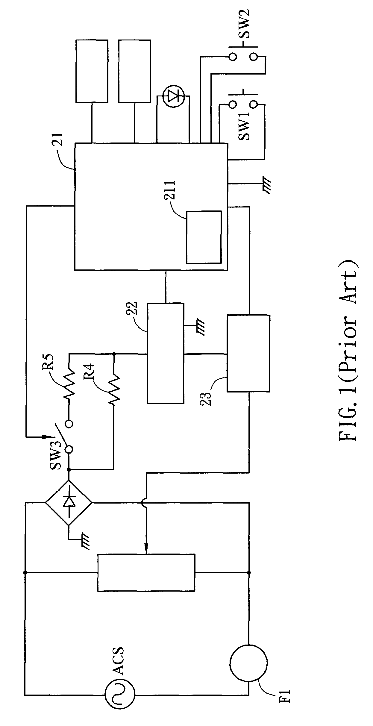
However, although the above-mentioned first and second types of control circuits have the advantage of simple design, they need many switch circuits for switching between different operation modes, which may result in very complex wiring and layout.
In this case, if the electronic equipment is damaged and the switch is needed to be replaced, it must consume a lot of working time for the replacement due to the complex wiring and layout.
However, the storage element 211 with larger capacity also has large volume, which will result in the waste of space, especially in the situation of no operation mode and function changes.

Method used


Image

  • Control circuit of cycling switch and control method thereof
  • Control circuit of cycling switch and control method thereof
  • Control circuit of cycling switch and control method thereof

Examples


Embodiment Construction

[0033]The present invention will be apparent from the following detailed description, which proceeds with reference to the accompanying drawings, wherein the same references relate to the same elements.

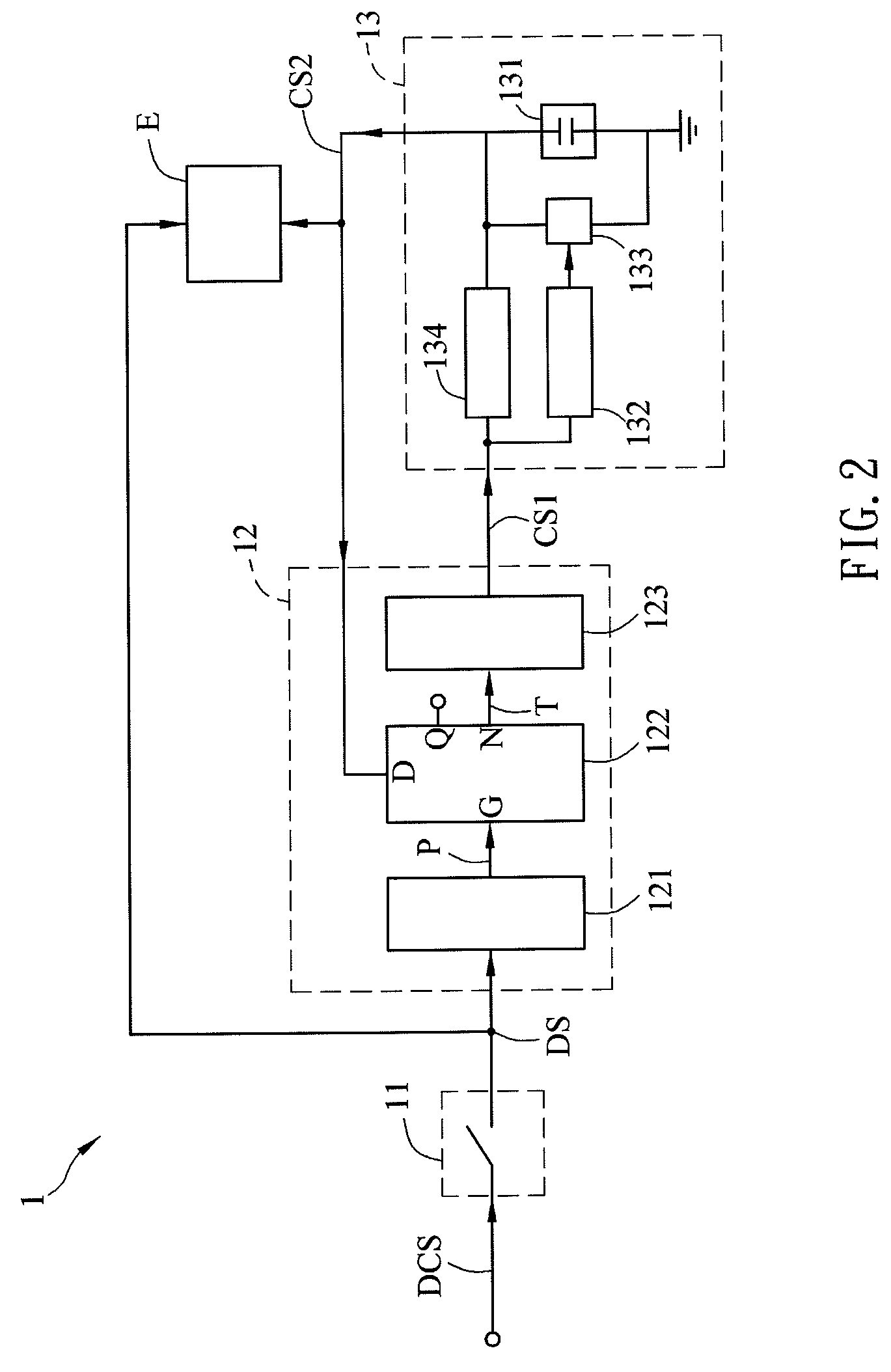
[0034]FIG. 2 is a schematic diagram of a control circuit 1 of a cycling switch according to one embodiment of the invention.

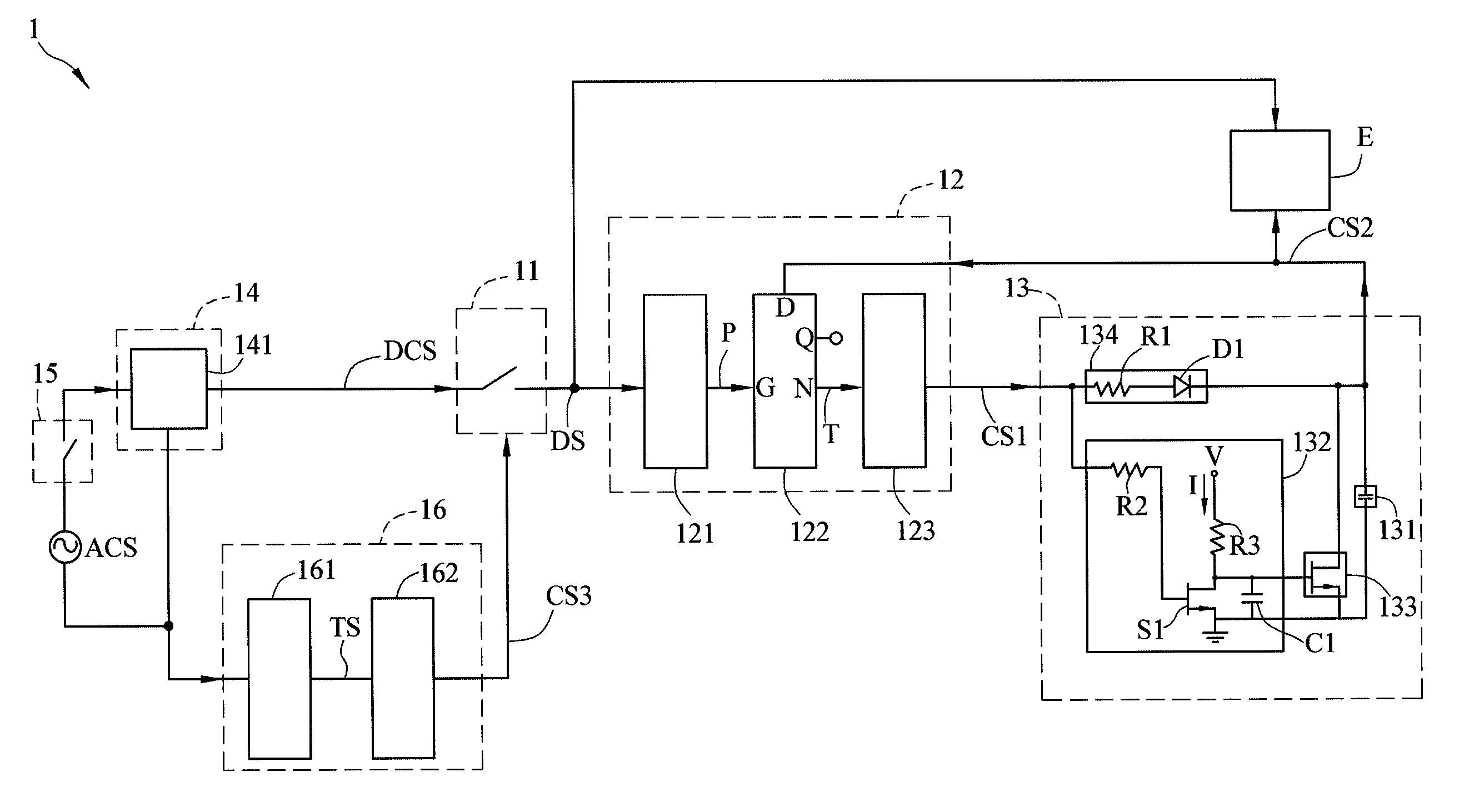
[0035]The control circuit 1 includes a switch loop 11, a first control loop 12, and a second control loop 13. The control circuit 1 is capable of controlling an electronic equipment E to operate in different operation modes and functions. The electronic equipment E may be a fan, a dryer or a lamp, and in the embodiment, the electronic equipment E is, for example but not limited to, a fan.

[0036]The switch loop 11 generates a driving signal DS to drive the electronic equipment E. In the embodiment, when the switch loop 11 is enabled, it outputs the driving signal DS according to a DC signal DCS to control the electronic equipment E to operate. Herein, the electroni...


PUM

PropertyMeasurementUnit
frequencyaaaaaaaaaa
poweraaaaaaaaaa
frequencyaaaaaaaaaa

Abstract

A control circuit of a cycling switch for controlling an electronic equipment includes a switch loop, a first control loop and a second control loop. The switch loop generates a driving signal to drive the electronic equipment. The first control loop is electrically connected with the switch loop and the electronic equipment respectively, and generates a first control signal according to a variation of the driving signal. The second control loop is electrically connected with the first control loop and the electronic equipment respectively. The second control loop has a storage unit which charges and discharges according to the first control signal, so that the second control loop generates a second control signal. The second control signal is inputted to the first control loop and controls the electronic equipment. A control method applied to the control circuit of the cycling switch is also disclosed.

Description

CROSS REFERENCE TO RELATED APPLICATIONS[0001]This Non-provisional application claims priority under 35 U.S.C. §119(a) on Patent Application No(s). 098143854 filed in Taiwan, Republic of China on Dec. 21, 2009, the entire contents of which are hereby incorporated by reference.BACKGROUND OF THE INVENTION[0002]1. Field of Invention[0003]The invention relates to a control circuit and a control method thereof. More particularly, the invention relates to a control circuit of a cycling switch and a control method thereof.[0004]2. Related Art[0005]The conventional control switch or circuit applied to the electronic equipment can be involved in the following three types. The first type is to use a mechanical control switch to control the electronic equipment, so that the operation modes and functions of the electronic equipment can be changed by switching the mechanical control switch. The second type is to use a plurality of control switches, so that the electronic equipment can be switched...

Claims


Application Information

Patent Timeline
Patent Type & Authority Patents(United States)
IPC IPC(8): H01H47/00H01H83/00H02H3/00
CPCH03K17/567Y10T307/826Y10T307/865Y10T307/858Y10T307/747Y10T307/832Y10T307/74
Inventor LIU, TE-CHUNGLEE, YI-HUA
Owner DELTA ELECTRONICS INC
Learn More