
System for and method of transferring charge to convert capacitance to voltage for touchscreen controllers

a touchscreen controller and capacitance conversion technology, applied in the field of human-to-machine interfaces, can solve the problems of reducing the maximum frame rate that can be supported, increasing latency, and reducing the signal-to-noise ratio, so as to reduce the requirement of offset canceling capacitance.

Active Publication Date: 2014-01-07
QUALCOMM INC
View PDF22 Cites 21 Cited by
  • Summary
  • Abstract
  • Description
  • Claims
  • Application Information

AI Technical Summary

Benefits of technology

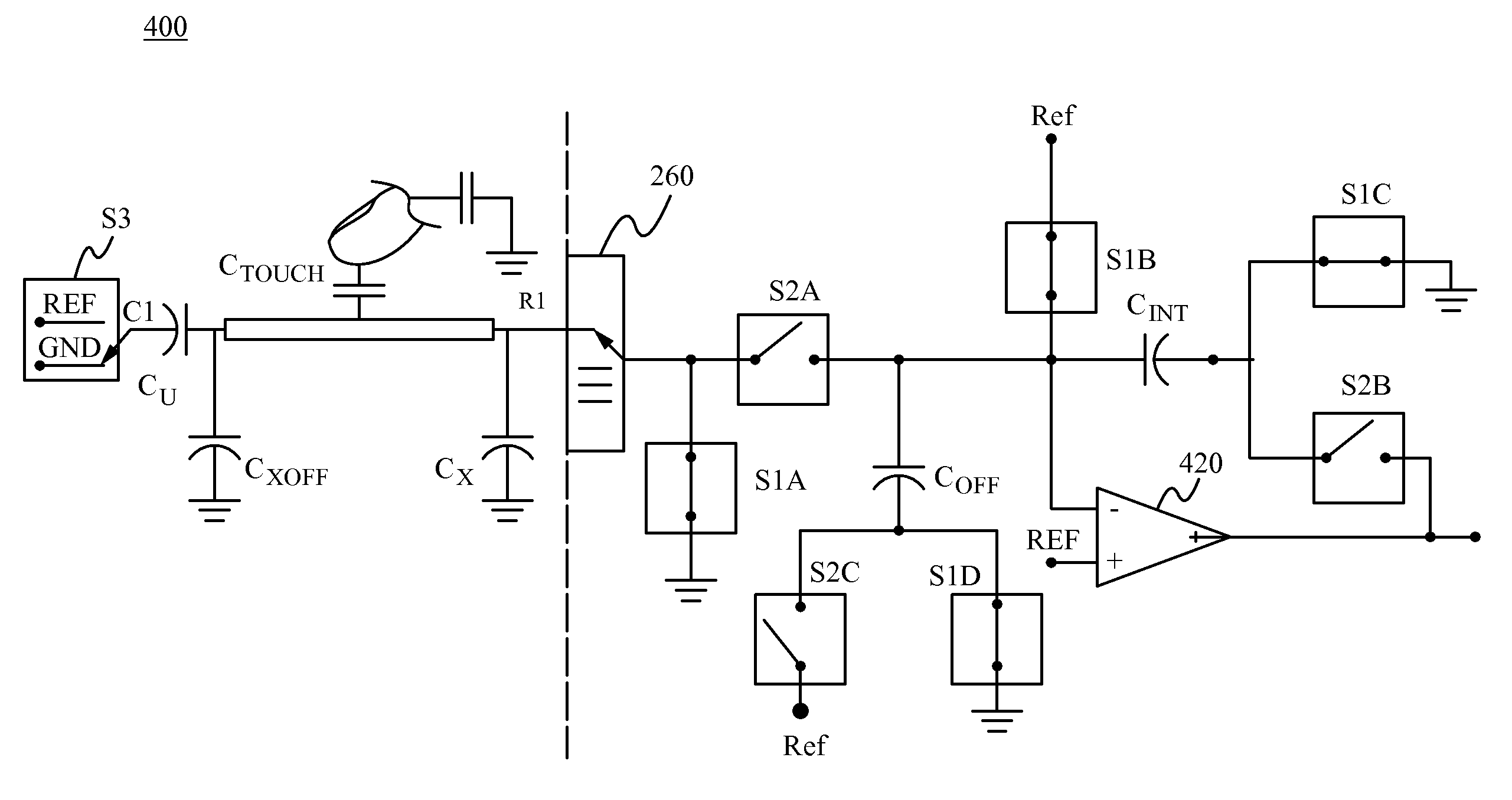
[0010]Touchscreen controller systems in accordance with the invention support mutual capacitance cancellation and selective mutual capacitance measurements between sensors, reducing the requirement of offset canceling capacitances. These touchscreen controller systems are also capable of eliminating ghost touches on a panel, a feature that is critical in detecting multi-touches without ambiguity. It does this without needing to take mutual capacitance measurements between each combination of row and column.
[0011]Touchscreen controller systems in accordance with the invention need only a single charge transfer cycle to detect capacitance changes that indicate the presence of an object. These touchscreen controller systems use on-chip integration capacitors, which are much smaller than external integration capacitors and can be charged and discharged more quickly. These touchscreen controller systems can support faster frame rates, can improve sensitivity, and require no external components for the sensors.
[0012]Touchscreen controller systems in accordance with the invention convert sensor capacitance of a touch screen panel to a directly proportional voltage. In a reset phase the systems are driven to ground and will not pick up noise from external sources. In one embodiment, except for one switch in the feedback path, all node voltages carry either a reference voltage or ground. This structure reduces the effect of charge injection because most of the charge injection results in a constant offset for the system, an offset that can be accommodated by calibration.

Problems solved by technology

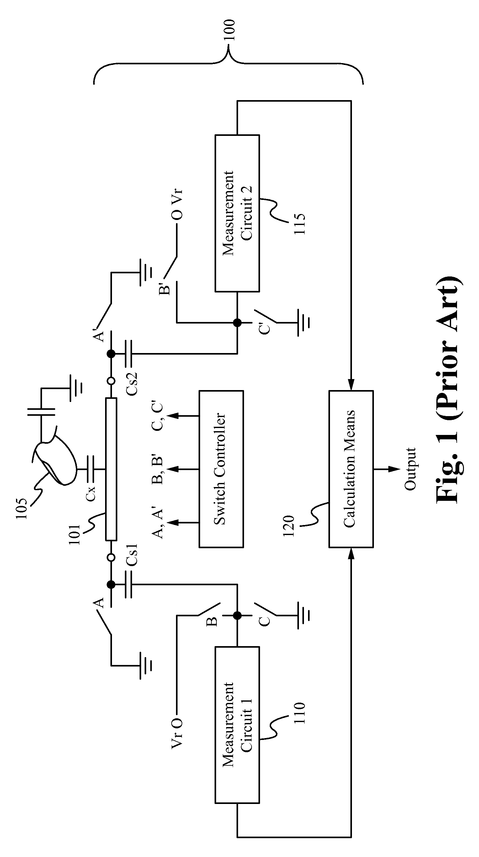
This increases the latency and thus reduces the maximum frame rate that can be supported.
As a result, the touchscreen 100 has limited sensitivity and a reduced signal-to-noise ratio.
The touchscreen 100, like other prior art capacitive touchscreens, also suffers from “ghosting,” during which the actual locations of simultaneous touches cannot be resolved.
The system is unable to easily distinguish between the real and ghost touches.
This ambiguity, and the processing needed to resolve it, increases exponentially with the number of simultaneous touches.
Systems that support mutual capacitance measurements require much more complex analog hardware, which results in higher power dissipation, lower throughput rate, larger die size, and more complex signal processing.

Method used


Image

  • System for and method of transferring charge to convert capacitance to voltage for touchscreen controllers
  • System for and method of transferring charge to convert capacitance to voltage for touchscreen controllers
  • System for and method of transferring charge to convert capacitance to voltage for touchscreen controllers

Examples


Embodiment Construction

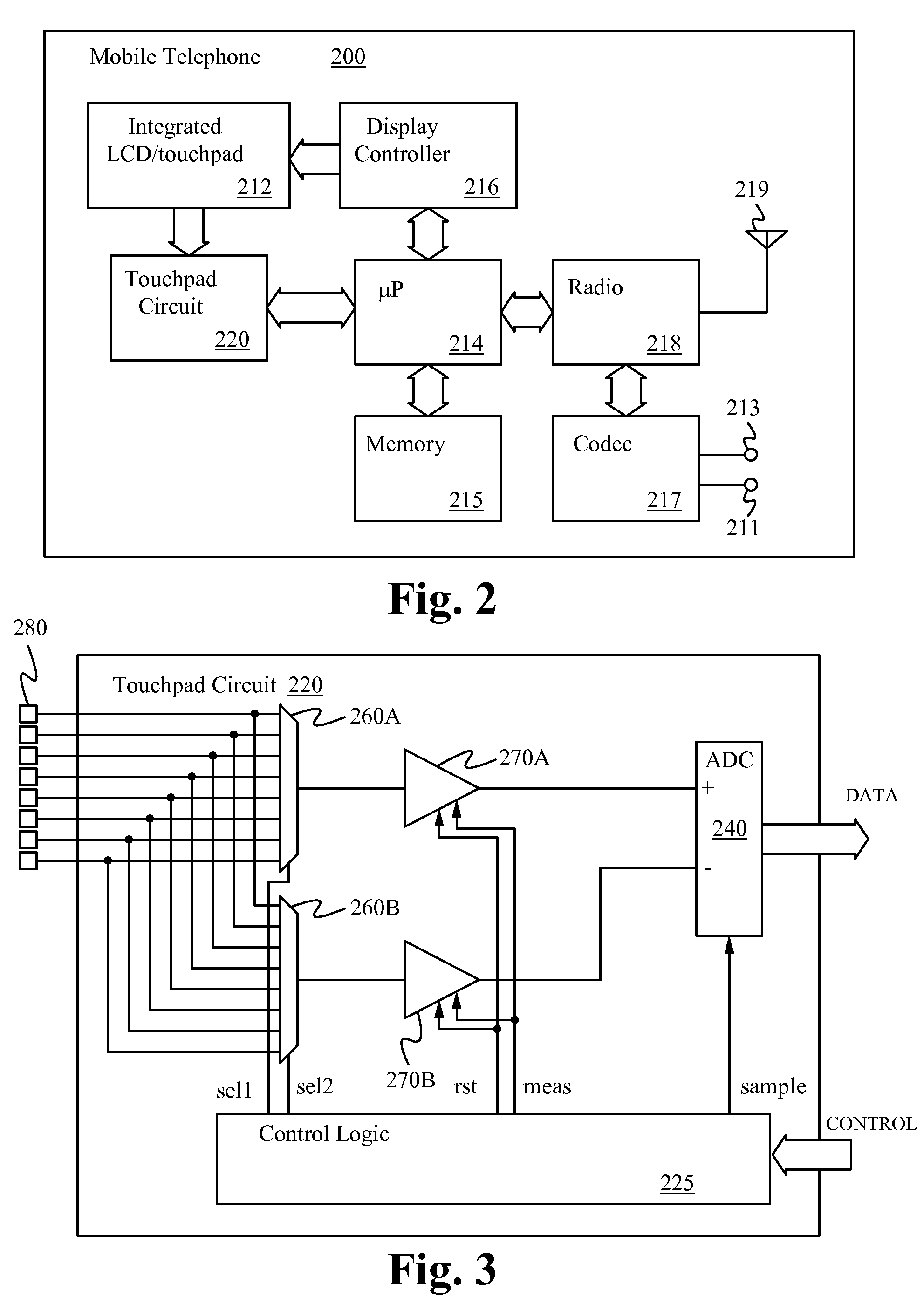
[0028]The present invention encompasses techniques for reducing or eliminating error in the output of capacitive sensor arrays such as touchpads, touchscreens, touch sliders and the like, including sensors that detect the presence and position of a stylus, as well as those that detect and determine finger position. While the illustrative embodiment described herein is applied in a mobile telephone, it is understood that capacitive touch sensors are used in a wide variety of devices. Examples of such devices are portable devices, such as personal digital assistants (PDA5), global positioning systems (GPS) receivers, as well as larger devices such as touchscreen enabled displays and computer systems, as well as appliances.

[0029]Referring now to FIG. 2, a mobile telephone 200 in accordance with one embodiment of the present invention is shown. The mobile telephone 200 includes a microprocessor (μP) 214 coupled to a memory 215 that stores program instructions for execution by the microp...


PUM


Abstract

A touchscreen controller system determines the actual locations of multiple simultaneous touches by eliminating mutual capacitance between adjacent rows and columns during self-capacitance measurements and selectively enabling mutual capacitance during mutual capacitance measurements. During the self-capacitance measurements, the controller system generates a set of candidate touch locations, which includes the locations of real and ghost touches. During the mutual capacitance measurements, only the locations in the candidate set are measured and, from these measurements, the actual touch locations are determined. By limiting the mutual capacitive measurements to only a small subset of the locations over the entire touch panel, real touch locations are determined on a linear order. Also, by using on-chip integration capacitors, embodiments of the invention are able to perform each measurement in a single cycle.

Description

RELATED APPLICATIONS[0001]This application claims priority under 35 U.S.C. §119(e) of the co-pending U.S. provisional patent application Ser. No. 61 / 326,830, filed Apr. 22, 2010, and titled “Differential Capacitive Touchpad Circuit and Method,” which is hereby incorporated by reference in its entirety.[0002]The following co-owned, co-filed, and co-pending applications, U.S. patent application Ser. No. 12 / 986,776, titled “Method and Apparatus for Improving Dynamic Range of a Touchscreen Controller,” U.S. patent application Ser. No. 12 / 986,881, titled “Noise Cancellation Technique for Capacitive Touchscreen Controller Using Differential Sensing,” U.S. patent application Ser. No. 12 / 986,991, titled “System Integration of Tactile Feedback and Touchscreen Controller for Near-Zero Latency Haptics Playout,” U.S. patent application Ser. No. 12 / 987,008, titled “Use of Random Sampling Technique to Reduce Finger-Coupled Noise,” and U.S. patent application Ser. No. 12 / 986,905, titled “Method an...

Claims


Application Information

Patent Timeline
Patent Type & Authority Patents(United States)
IPC IPC(8): G06F3/041G06F3/045
CPCH03K17/96H03K2217/96062G06F2203/04104G06F3/044G06F3/0416G06F3/041662G06F3/0446
Inventor JOHARAPURKAR, ASHUTOSH RAVINDRAKODUR, KARTHIKEYAREDDY, VENUGOPALCHAN, PATRICK
Owner QUALCOMM INC
Learn More