
Dual homed E-spring protection for network domain interworking

a network domain and protection technology, applied in data switching networks, frequency-division multiplexes, instruments, etc., can solve problems such as destabilization of networks, and achieve the effects of ensuring loop freeness, simple and robust protection switching functionality, and high speed failure recovery

Active Publication Date: 2014-01-07
CIENA
View PDF19 Cites 7 Cited by
  • Summary
  • Abstract
  • Description
  • Claims
  • Application Information

AI Technical Summary

Benefits of technology

The present invention uses a ring network routing scheme to control traffic forwarding through a dual-homed connection, which provides simple and robust protection switching, high-speed failure recovery, and loop freeness without the need for complex algorithms to coordinate the behavior of peering nodes. This enables effective and efficient network protection and recovery.

Problems solved by technology

However, taken together the two paths form a loop which, under some circumstances, could destabilize the network.

Method used


Image

  • Dual homed E-spring protection for network domain interworking
  • Dual homed E-spring protection for network domain interworking
  • Dual homed E-spring protection for network domain interworking

Examples


Embodiment Construction

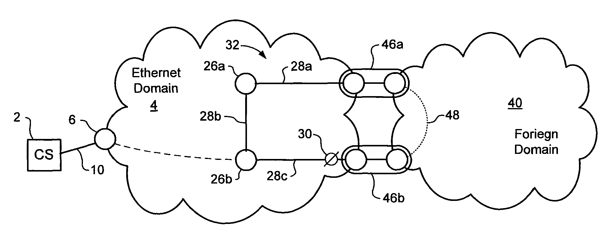
[0017]The present invention provides a method of supporting dual homed interworking between an Ethernet network domain and a foreign network domain. Embodiments of the invention are described below, by way of example only, with reference to FIGS. 2-6.

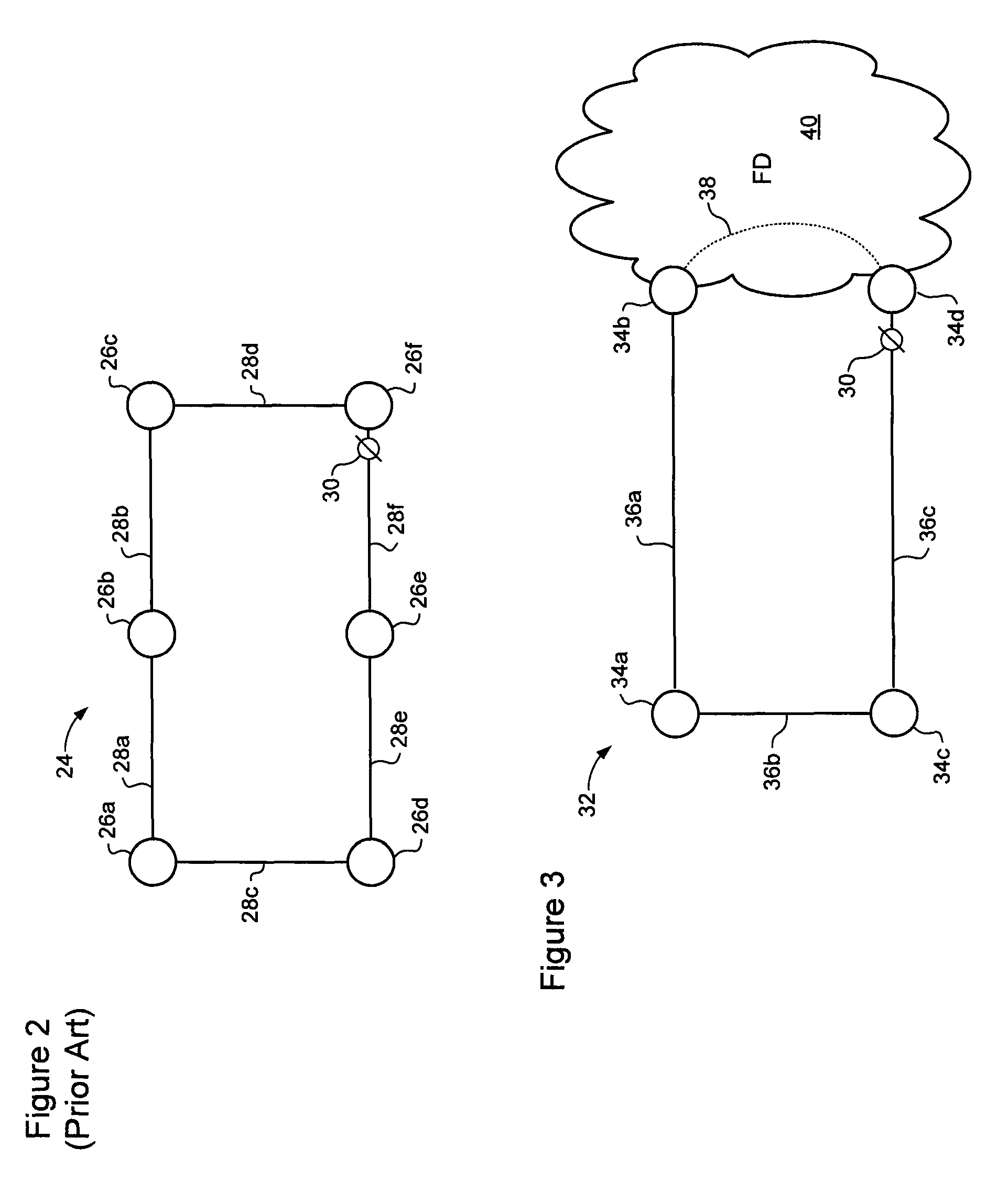
[0018]ITU-T SG15 / Q9 recommendation G.8032 (June, 2008) describes protection switching in an Ethernet ring. Referring to FIG. 2, an Ethernet ring 24 is an Ethernet network comprising nodes 26 and links 28 connected together in a ring topology. One of the links of the ring is designated as a Ring Protection Link (RPL), and is disabled during normal operation of the ring by placing a channel block 30 on that link. Typically, a channel block 30 is imposed at a node at one end of the RPL, which node may then be referred to as the RPL Owner. In some cases, the channel block 30 may, for example, comprise a policy that prevents packets of the ring from being forwarded through a port hosting the RPL. With such a channel block 30 in place, the ri...


PUM


Abstract

A system for controlling packet forwarding through a dual-homed connection between first and second network domains, the dual-homed connection including two peer nodes connected to the first and second network domains. A sub-ring network is instantiated in the first network domain, and includes at least two nodes connected in a linear topology between a pair of end-nodes. Each end-node corresponds with a respective one of the peer nodes. A virtual link through the second network domain for conveys traffic of the sub-ring network between the peer nodes, and closes the sub-ring network to define a ring topology. Each of the nodes of the sub-ring network is controlled to forward packets of the sub-ring network in accordance with a ring network routing scheme.

Description

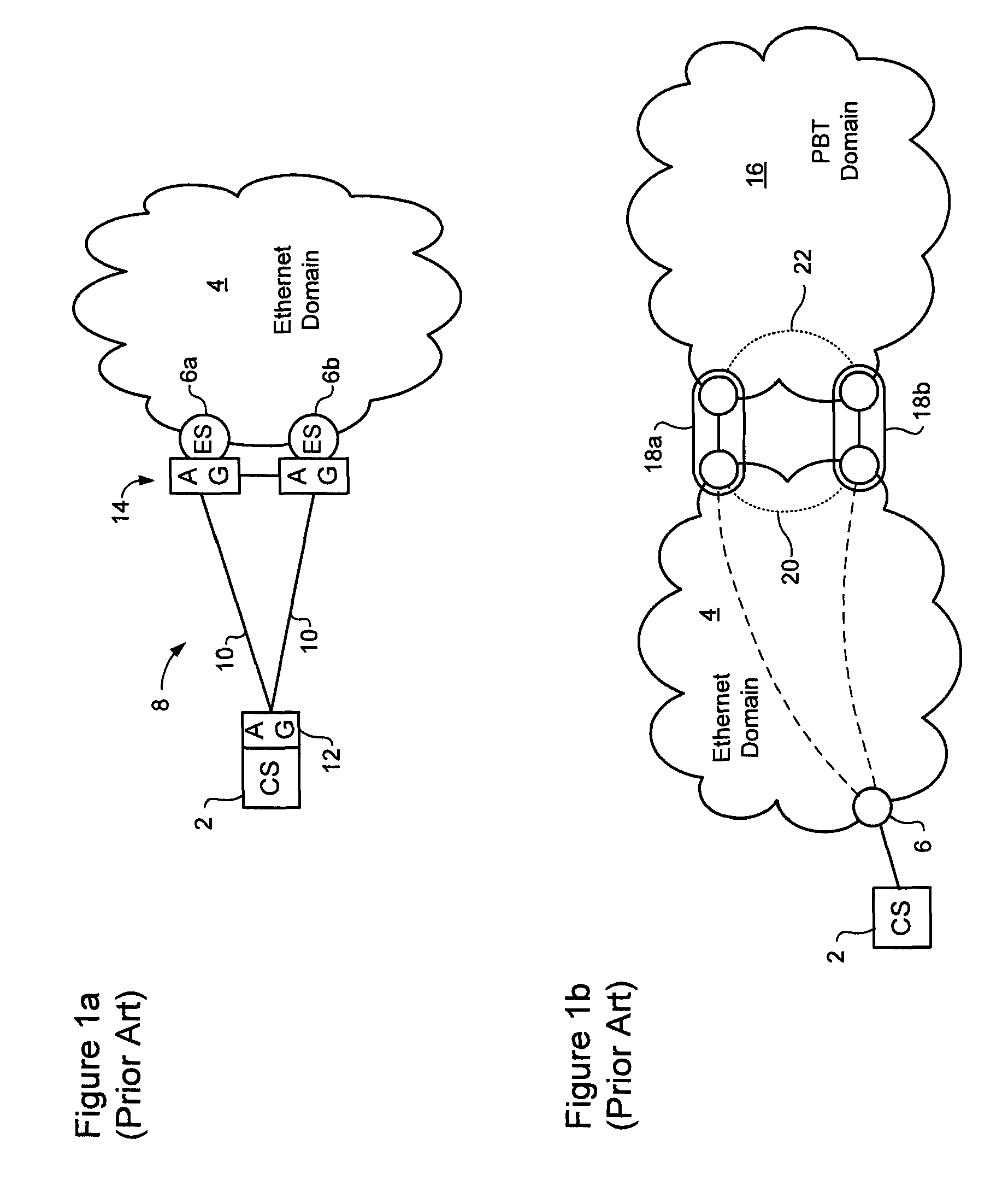
TECHNICAL FIELD[0001]The present invention relates to management of traffic forwarding in packet networks, and in particular to methods of preventing loops in multicast routes mapped through a packet network.BACKGROUND OF THE INVENTION[0002]Ethernet is increasingly popular as a transport network for high speed Wide Area Network (WAN) communications. Various techniques have been developed to enable the deployment of Ethernet transport networks with a mesh topology. Among other things, these enable the provisioning of topologically diverse paths for traffic protection, while preventing the formation of loops within the network.[0003]Referring to FIG. 1a, Split Multi Link Trunking (SMLT), which is described in Applicant's U.S. Pat. No. 7,269,132 provides a technique by which a client system (CS) 2 can be connected to an Ethernet network domain 4 though a pair of peer Ethernet Switches (ESs) 6a-b. In very general terms, a Split Link Aggregation Group (SLAG) 8 is defined, which comprises...

Claims


Application Information

Patent Timeline
Patent Type & Authority Patents(United States)
IPC IPC(8): G06F15/173G01R31/08H04L12/28H04L45/18
CPCH04L45/18H04L12/462H04L12/437
Inventor ABDULLAH, BASHARHOLNESS, MARCBOTTORFF, PAULST-DENIS, BERNARD
Owner CIENA
Learn More