Needle bearing

a technology of needle bearings and needles, which is applied in the direction of shafts and bearings, rotary bearings, rolling contact bearings, etc., can solve the problems of inability to hold needles, insufficient deformation amount, plastic deformation, etc., and achieve sufficient strength, sufficient deformation amount, and prevent plastic deformation

Active Publication Date: 2014-01-14
NSK LTD
View PDF6 Cites 5 Cited by
  • Summary
  • Abstract
  • Description
  • Claims
  • Application Information

AI Technical Summary

Benefits of technology

[0025]In a needle bearing according to the present invention, a cage is circumferentially provided with a plurality of elastic deformation portions that are allowed to be circumferentially shrunk or extended, and the elastic deformation portions are formed symmetrically with respect to an axial intermediate portion, thus making it possible to provide the circumferentially shrinkable or extensible cage capable of preventing plastic deformation and capable of ensuring both of a sufficient strength for axial torsion and a sufficient deformation amount.

Problems solved by technology

Actually, when a cage thickness cannot be sufficiently ensured in the cage described in Patent Document 1, there occurs a problem that the cage causes plastic deformation and cannot successfully hold the needles.
On the other hand, the cage described in Patent Document 2 is capable of ensuring a sufficient strength for axial torsion but might be incapable of obtaining a sufficient deformation amount for a radial dimension of the flange because an elastic deformation portion is provided at only one circumferential position.

Method used


Image

  • Needle bearing
  • Needle bearing
  • Needle bearing

Examples


first embodiment

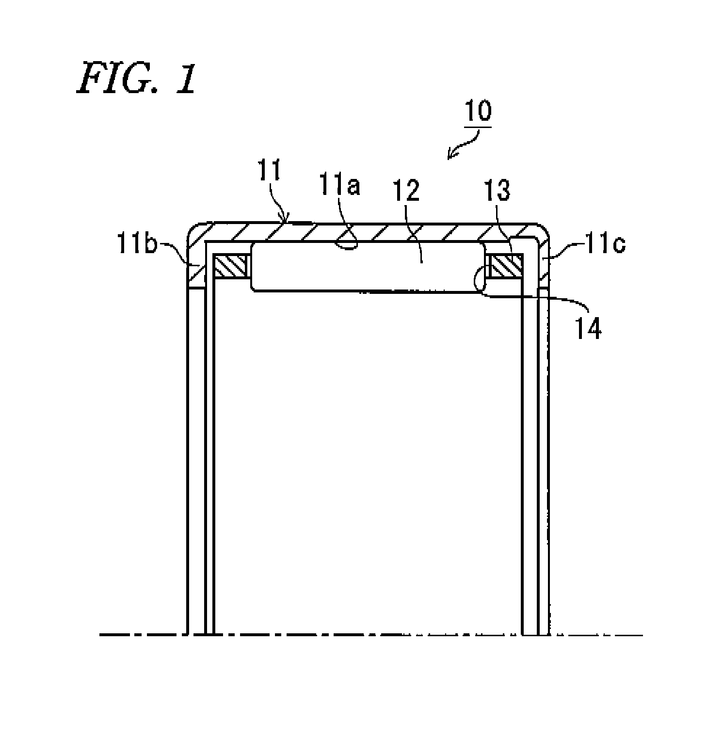
[0038]A drawn cup needle bearing 10 according to a first embodiment is placed, for example, between gear trains in an AT, between a gear shaft and a housing or at a lateral position with respect to an oil pump gear, and is reduced in thickness at a bearing cross-sectional height of about 1.0 mm to about 3.5 mm. As illustrated in FIG. 1, this drawn cup needle bearing 10 includes: a drawn cup (collared outer ring) 11 serving as a bearing ring having, at its inner peripheral surface, a raceway surface 11a and having, at its end portions, a pair of inward flanges 11b, 11c; a plurality of needles 12 placed inside the drawn cup 11 so as to be rolled along the raceway surface 11a of the drawn cup 11; and a cage 13 having a plurality of pockets 14 for holding the plurality of needles 12, thereby rotatably supporting an unillustrated shaft (or an inner ring member).

[0039]The drawn cup 11 is formed into a cylindrical shape as a whole by performing plastic working such as drawing on a material...

second embodiment

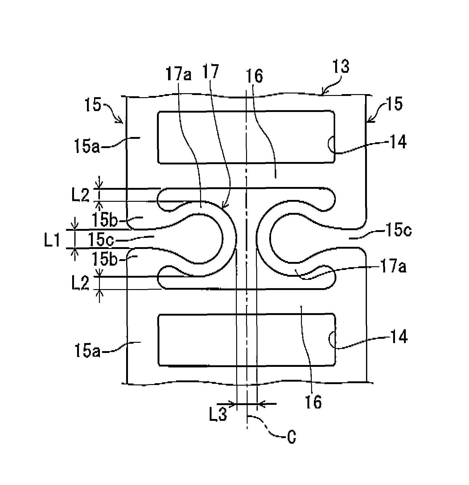
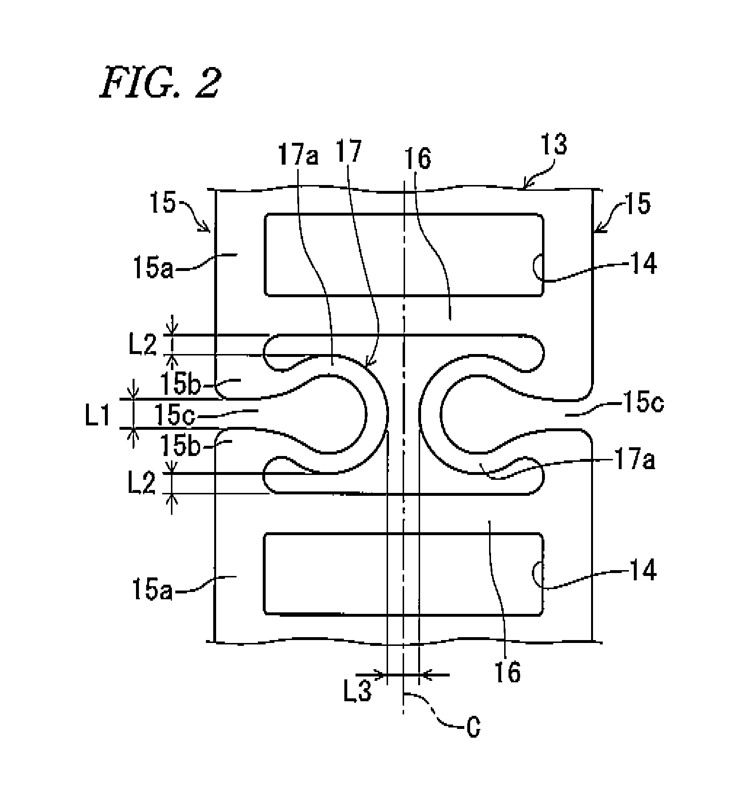
[0051]FIG. 8 illustrates a cage 13′ of a drawn cup needle bearing according to a second embodiment of the present invention. This cage 13′ is also circumferentially provided with a plurality of (four in the present embodiment) elastic deformation portions 17′, which are allowed to be circumferentially shrunk or extended, at positions between circumferentially adjacent columns 16, 16 where cuts 15c are formed.

[0052]With end portions 15b, 15b of circumferentially adjacent arc-shaped portions 15a, 15a serving as base ends, the elastic deformation portions 17′ each have a pair of elastic deformation pieces 17a, 17a including: axially extended portions 17b, 17b extended axially inward and substantially linearly from the end portions 15b, 15b; and circumferential connection portions 17c, 17c through which the axially extended portions 17b, 17b are substantially linearly connected to each other in a circumferential direction. The pair of elastic deformation pieces 17a, 17a have the same sh...


PUM


Abstract

A needle bearing including a cage that is shrinkable or extensible in a circumferential direction, which can prevent plastic deformation and ensure both of a sufficient strength for axial torsion and a sufficient deformation amount. In a drawn cup needle bearing, a cage includes a plurality of elastic deformation portions along a circumferential direction thereof, which are shrunk in the circumferential direction. The elastic deformation portions are formed symmetrically with respect to an intermediate portion C in an axial direction of the cage.

Description

CROSS-REFERENCE TO RELATED APPLICATIONS[0001]The present application is based on Japanese Patent Application No. 2009-294136 filed on Dec. 25, 2009, the contents of which are incorporated herein by reference.TECHNICAL FIELD[0002]The present invention relates to needle bearings, and in particular relates to needle bearings applied to an automobile drive system including an automatic transmission (AT), a manual transmission (MT), a differential gear, a transfer and a detent, an engine crankshaft support, an engine camshaft support, and an automobile steering system.BACKGROUND ART[0003]In an automatic transmission or the like of an automobile, instead of a slide bearing (bushing), a drawn cup needle bearing having a similar cross-sectional height has recently been used at a position where a radial load is received. As illustrated in FIG. 10, a drawn cup needle bearing 100 includes: a drawn cup outer ring 101 having, at its inner peripheral surface, a raceway surface 101a and having, at...

Claims


Application Information

Patent Timeline
Patent Type & Authority Patents(United States)
IPC IPC(8): F16C33/48
CPCF16C33/4635F16C19/466F16C33/4694F16C2326/01F16C2361/61F16C33/48F16C33/54F16C39/02
Inventor KONDOU, YUTAKA
Owner NSK LTD
Why Eureka
Try Eureka