Radiation imaging system and method for detecting positional deviation

a radiation imaging and positional deviation technology, applied in the field of radiation imaging systems, can solve the problems of complex and expensive x-ray imaging systems, inability to have sufficient contrast, and inability to detect the positional deviation easily and precisely

Inactive Publication Date: 2014-01-21
FUJIFILM CORP
View PDF7 Cites 50 Cited by
  • Summary
  • Abstract
  • Description
  • Claims
  • Application Information

AI Technical Summary

Benefits of technology

[0014]An object of the present invention is to easily and precisely detect positional deviation between gratings due to time degradation, in a radiation imaging system for carrying out phase imaging with the use of the gratings.
[0023]According to the present invention, the positional deviation between the first grating and the intensity modulator is evaluated based on the characteristic value of the intensity modulation signal, which is obtained on a pixel-by-pixel basis from the plural fringe images captured by the radiation image detector. Thus, it is possible to easily and precisely detect the positional deviation due to time degradation.

Problems solved by technology

Thus, the X-ray image of living soft tissue, soft material, or the like, cannot have sufficient contrast.
Thus, the X-ray image of the arthrosis hardly has sufficient contrast.
Thus, the X-ray imaging system becomes complicated and expensive.
However, the patent document does not describe to detect the positional deviation amount between the first and second diffraction gratings from the offset amount Δ(x, y).
Thus, it becomes difficult to precisely calculate the positional deviation amount from the offset amount Δ(x, y).

Method used


Image

  • Radiation imaging system and method for detecting positional deviation
  • Radiation imaging system and method for detecting positional deviation
  • Radiation imaging system and method for detecting positional deviation

Examples


first embodiment

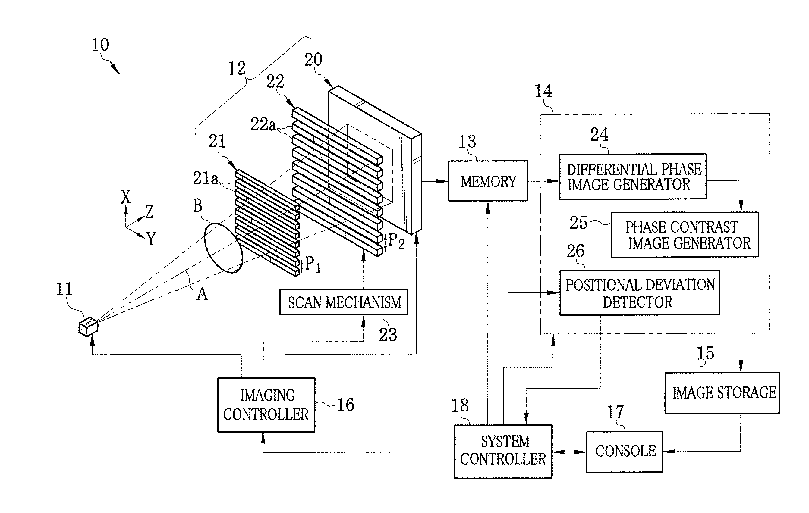
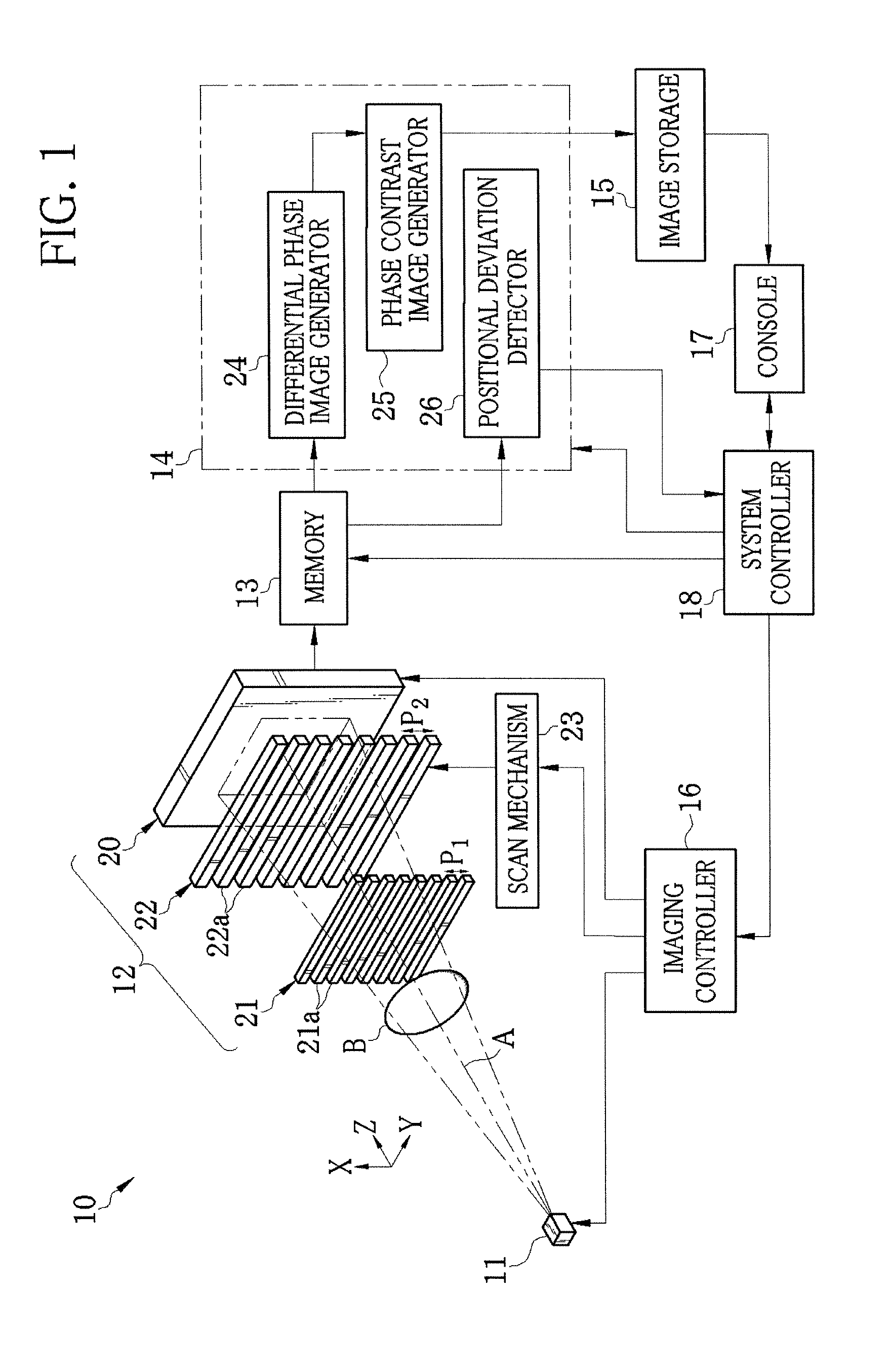
[0036]As shown in FIG. 1, an X-ray imaging system 10 according to a first embodiment is constituted of an X-ray source 11 for emitting X-rays, an imaging unit 12, a memory 13, an image processor 14, an image storage 15, an imaging controller 16 for controlling the X-ray source 11 and the imaging unit 12, a console 17 including an operation unit and a monitor, and a system controller 18 for carrying out control of the entire X-ray imaging system 10 based on an operation signal inputted from the console 17. The imaging unit 12 is disposed so as to face the X-ray source 11, and detects the X-rays that have been emitted from the X-ray source 11 and passed through an object B, to produce image data. The memory 13 stores the image data outputted from the imaging unit 12. The image processor 14 produces a phase contrast image from plural frames of image data stored on the memory 13. The image storage 15 stores the phase contrast image produced by the image processor 14.

[0037]The X-ray sour...

second embodiment

[0099]In the above first embodiment, if the length from the X-ray source 11 to the FPD 20 is elongated, the G1 image is blurred due to a size (0.1 mm to 1 mm, in general) of the X-ray focus 11a. The blur causes degradation in the image quality of the phase contrast image. For this reason, a multi-slit (source grating) 50 may be disposed just behind the X-ray focus 11a, as shown in FIG. 10.

[0100]The multi-slit 50 is an absorption grating that is similar to the first and second absorption gratings 21 and 22. In the multi-slit 50, a plurality of X-ray shield members 50a extending in the Y direction are periodically arranged in the X direction at a predetermined grating pitch P0. This multi-slit 50 partly blocks the X-rays emitted from the X-ray source 11 to reduce the effective focus size in the X direction, and forms a number of point sources (distributed light sources) in the X direction, in order to prevent the blur of the G1 image.

[0101]The grating pitch P0 of the multi-slit 50 has...

third embodiment

[0106]In the above first and second embodiments, the first and second absorption gratings 21 and 22 linearly project the X-rays that have passed through the slits. However, the present invention is applicable to a radiation imaging apparatus (refer to International Publication No. WO2004 / 058070) in which the slits diffract the X-rays to produce the so-called Talbot effect. In this case, however, the length L2 between the first and second absorption gratings 21 and 22 has to be set at the Talbot distance. Also, in this case, a phase grating (phase diffraction grating) is usable instead of the first absorption grating 21. This phase grating projects to the second absorption grating 22 the fringe image (self image) produced by the Talbot effect.

[0107]The difference between the phase grating and the absorption grating is only the thickness of an X-ray absorptive material (X-ray shield members). The X-ray shield members of the absorption grating have a thickness of approximately 30 μm or...


PUM


Abstract

A radiation imaging system includes an X-ray source, first and second absorption gratings disposed in a path of X-rays emitted from the X-ray source, and an FPD. The second absorption grating is slid stepwise in an X direction relative to the first absorption grating. Whenever the second absorption grating is slid, the FPD captures a fringe image. From the captured plural fringe images, an intensity modulation signal of each pixel is obtained. A positional deviation detector calculates an amplitude value of the intensity modulation signal. The positional deviation detector compares a measurement of the amplitude value with predetermined first and second threshold values. If the measurement is less than the first threshold value, a warning signal is outputted. If the measurement is less than the second threshold value, an error signal is outputted.

Description

BACKGROUND OF THE INVENTION[0001]1. Field of the Invention[0002]The present invention relates to a radiation imaging system that carries out radiography with the use of radiation such as X-rays. More specifically, the present invention relates to the radiation imaging system for phase imaging that is provided with gratings disposed between a radiation source and a radiation image detector, and a method for detecting positional deviation between the gratings.[0003]2. Description Related to the Prior Art[0004]X-rays are used as a probe for imaging inside of an object without incision, due to the characteristic that attenuation of the X-rays depends on the atomic number of an element constituting the object and the density and thickness of the object. Radiography with the use of the X-rays is widely available in fields of medical diagnosis, nondestructive inspection, and the like.[0005]In a conventional X-ray imaging system for capturing an X-ray image of the object, the object to be e...

Claims


Application Information

Patent Timeline
Patent Type & Authority Patents(United States)
IPC IPC(8): A61B6/00
CPCA61B6/484A61B6/06A61B6/4233A61B6/4021A61B6/586A61B6/4291A61B6/00A61B6/582
Inventor ISHII, HIROYASU
Owner FUJIFILM CORP
Why Eureka
Try Eureka