Mask comfort diagnostic method

a mask and comfort technology, applied in the field of patient evaluation methods, can solve the problems of minor red marks, open sores, and all patient interface masks generate some level of discomfort, and achieve the effects of reducing blood flow, effective visualizing, and reducing blood flow

Active Publication Date: 2014-01-21
KONINKLIJKE PHILIPS ELECTRONICS NV
View PDF7 Cites 7 Cited by
  • Summary
  • Abstract
  • Description
  • Claims
  • Application Information

AI Technical Summary

Benefits of technology

[0011]Accordingly, it is an object of the present invention to provide a method that overcomes the shortcomings of conventional mask fitting methods. This object is achieved according to one embodiment of the present invention by effectively visualizing, for instance, reduced blood flow, using, for example and without limitation, high resolution thermal imaging, such that slight variations in skin surface temperature are apparent. By combining thermal imaging with time lapse techniques, it is possible to evaluate (e.g., without limitation, by a clinician; by a suitable apparatus) potential for pressure sores or discomfort of patients.

Problems solved by technology

It is generally believed that all patient interface masks generate some level of discomfort by applying pressure to the patient's face.
This pressure can lead to minor red marks (e.g., a minimum level of discomfort) or open sores (e.g., a maximum discomfort).
Population variations add complexity to this problem.
Further complexity is added from the effects of shear force.
The dermis of a patient is at risk from excessive strain from pressure.
The various convoluted capillary tubes can easily be bent over (e.g., kinked) by shear force which results in the occlusion of blood flow.
Normal stress pressure on the capillary tubes can also cause the restriction or occlusion of blood flow.
It is known that when mechanical stress is applied to the tissues of a person having one or more conditions relating to skin temperature, age, infection, body type, collagen formation, nutrition, and fibrinolytic activity, that it is likely that a pressure sore will result.
Light finger pressure can cause blanching.

Method used


Image

  • Mask comfort diagnostic method
  • Mask comfort diagnostic method
  • Mask comfort diagnostic method

Examples


example 1

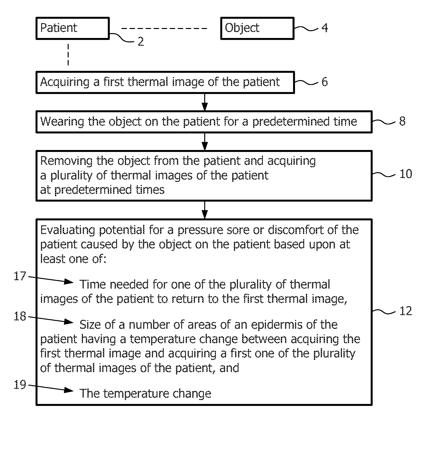
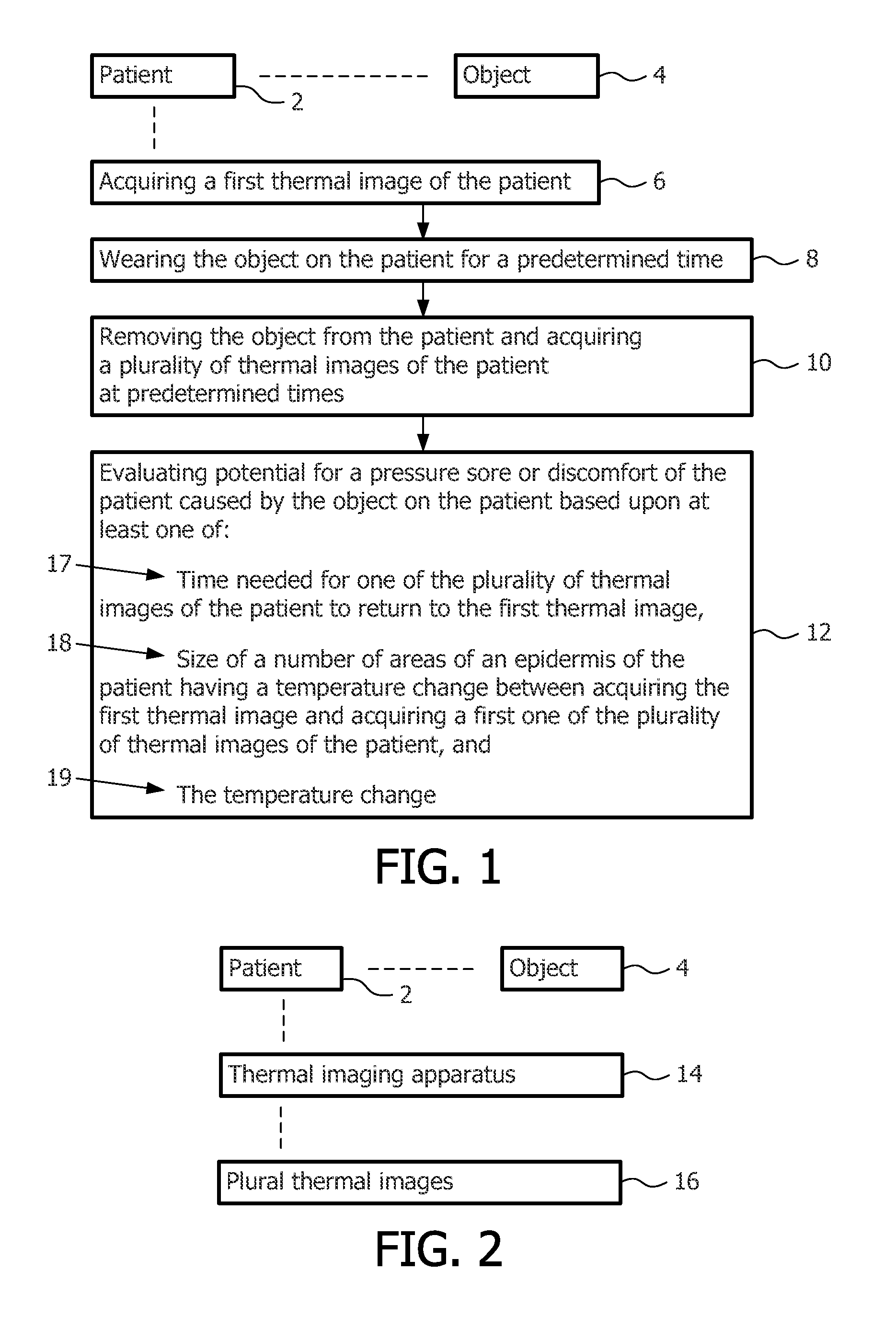
[0026]Referring to FIGS. 1 and 2, the example evaluation method includes four example steps using a suitable thermal imaging apparatus 14, which provides a plurality of (e.g., without limitation, color, grayscale, raw temperature data (e.g., matrix data)) thermal images 16.

[0027]First, at 6, a baseline thermal image of patient 2 is acquired. This outlines initial temperature variations based on physiology and can be done by a clinician or an assistant, or can be automated or semi-automated.

[0028]Second, at 8, patient 2 wears object 4 (e.g., without limitation, a test mask) for a suitable predetermined time period. This predetermined time period can be timed by a clinician or an assistant, or can be automated or semi-automated.

[0029]Third, at 10, upon removal of example test mask 4, thermal images are acquired at suitable predetermined time intervals. This acquisition can be done by a clinician or an assistant, or can be automated or semi-automated.

[0030]Fourth, at 12, the time neede...

example 2

[0032]Steps 6,8,10,12 can, for example, be fully automated in the form of an example kiosk (not shown). For example, a “picture booth” type kiosk (not shown) can employ indicators for what to do to acquire the baseline thermal image of patient 2, when to initially put example test mask 4 on patient 2, when to take the example test mask 4 off patient 2, what to do to acquire thermal images at predetermined time intervals, and optionally when the testing is concluded after a thermal image returns to baseline thermal image of step 6. For example, suitable equipment (not shown) can time and decide that the thermal image returns to the baseline thermal image by employing suitable automatic image comparison tools (not shown) and / or facial recognition software (not shown). Such equipment can also determine the relative size and temperature change of the affected areas as indicators of potential pressure sores or discomfort by employing suitable automatic image analysis tools (not shown).

example 3

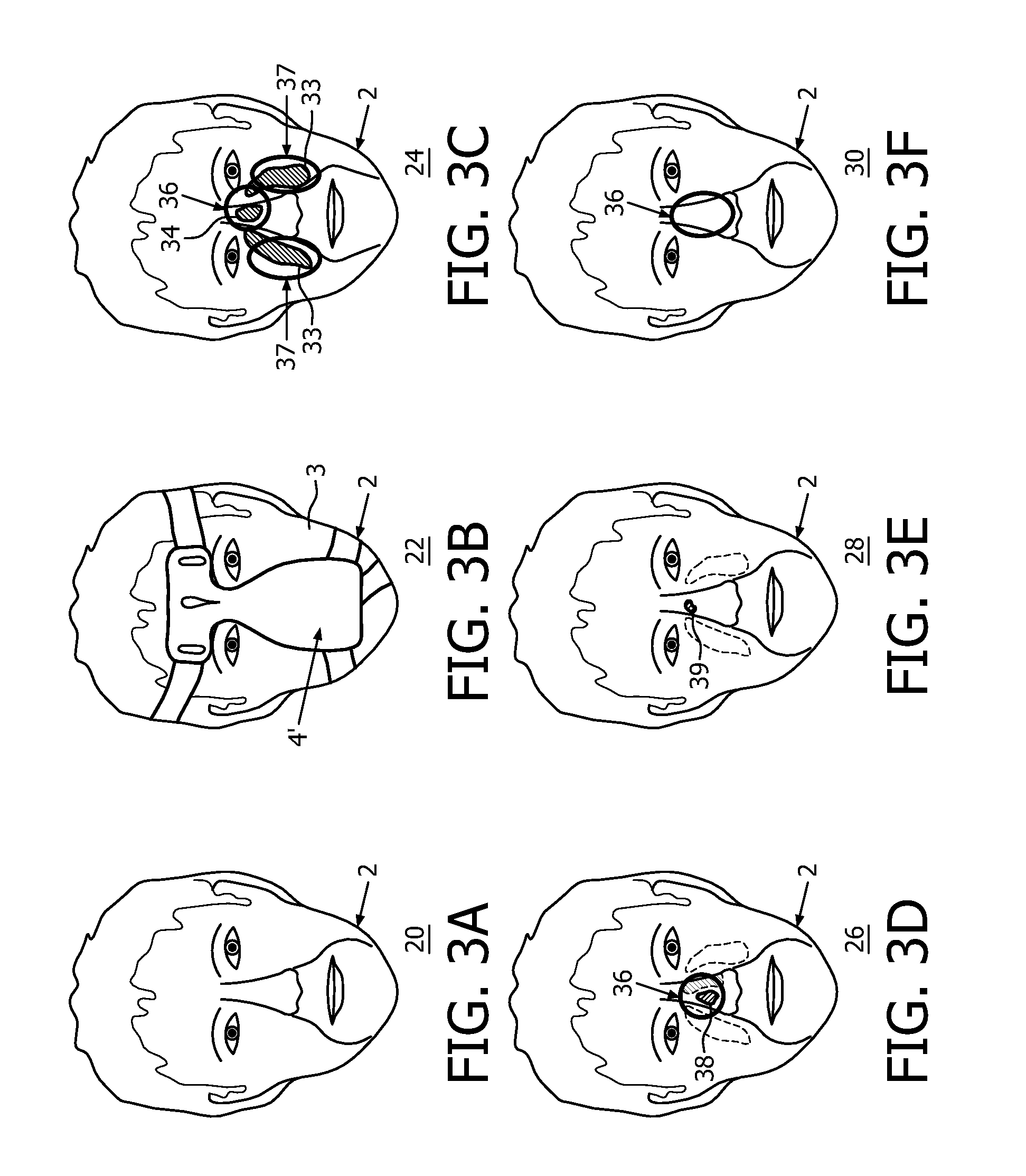
[0033]The predetermined time period of step 8 can be as short as about 5 minutes to about 10 minutes, the latter of which is the approximate time corresponding to representations of thermal images 20, 22, 24, 26, 28, 30 of FIGS. 3A-3F and representations of thermal images 40, 42, 44, 46, 48, 50 of FIGS. 4A-4F. Example thermal images 60, 62, 64, 66, 68, 70 are shown in FIGS. 5A-5F corresponding to respective FIGS. 3A-3F, and example thermal images 80, 82, 84, 86, 88, 90 are shown in FIGS. 6A-6F corresponding to respective FIGS. 4A-4F.


PUM


Abstract

A method of evaluating potential for discomfort of a patient (2) caused by an object (4) on the patient. The method includes acquiring (6) a first thermal image (20;40) of the patient, and wearing the object for a predetermined time. The object is removed and a plurality of thermal images (16, 24, 26, 28, 30, 44, 46, 48, 50) of the patient are acquired at predetermined times. The potential for a pressure sore or discomfort is evaluated (12) based upon at least one of the time (17) needed for one of the plurality of thermal images of the patient to return to the first thermal image, size (18) of a number of areas of an epidermis having a temperature change (19) between acquiring the first thermal image and acquiring a first one of the thermal images, and the temperature change.

Description

CROSS-REFERENCE TO RELATED APPLICATIONS[0001]This patent application claims the priority benefit under 35 U.S.C. §119(e) of U.S. Provisional Application No. 61 / 260,039 filed on Nov. 11, 2009, the contents of which are herein incorporated by reference.BACKGROUND OF THE INVENTION[0002]1. Field of the Disclosure[0003]The invention pertains to evaluation methods for patients, and, in particular, to such methods of evaluating potential for pressure sores or discomfort of patients.[0004]2. Description of the Related Art[0005]In order to maximize compliance for continuous positive airway pressure (CPAP) therapy, for example, patient interface masks are designed to optimize comfort for the patient. Currently, patient comfort is assessed by return calls or follow up treatments after the patient has been on CPAP therapy for some time period.[0006]It is generally believed that all patient interface masks generate some level of discomfort by applying pressure to the patient's face. This pressur...

Claims


Application Information

Patent Timeline
Patent Type & Authority Patents(United States)
IPC IPC(8): A61B6/00
CPCA61M2205/3306A61M16/06A61M2016/0661A61M2205/3368A61B5/015A61B5/447A61M16/0633
Inventor SMITH, DAVID, W.
Owner KONINKLIJKE PHILIPS ELECTRONICS NV
Why Eureka
Try Eureka