Piezoelectric resonator having mesa type piezoelectric vibrating element

a piezoelectric vibrating element and piezoelectric resonator technology, applied in the field of piezoelectric resonators, can solve the problems of reducing productivity, difficult to practically increase the digging quantity up to the threshold value, and reducing the productivity of the piezoelectric resonator itself, so as to improve the productivity of the piezoelectric vibrating element and the productivity of the piezoelectric resonator

Active Publication Date: 2014-01-28
SEIKO EPSON CORP
View PDF23 Cites 11 Cited by
  • Summary
  • Abstract
  • Description
  • Claims
  • Application Information

AI Technical Summary

Benefits of technology

[0027]With such a characteristic, formation of the protruding portion and formation of the vibrating portion can be realized through a one-time etching process

Problems solved by technology

In the mesa type piezoelectric vibrating element which has a level difference on the boundary of the vibrating portion and the peripheral portion, however, spurious vibrations, such as flexure vibrations which are unnecessary vibrations, increase with the influence of t

Method used


Image

  • Piezoelectric resonator having mesa type piezoelectric vibrating element
  • Piezoelectric resonator having mesa type piezoelectric vibrating element
  • Piezoelectric resonator having mesa type piezoelectric vibrating element

Examples


Embodiment Construction

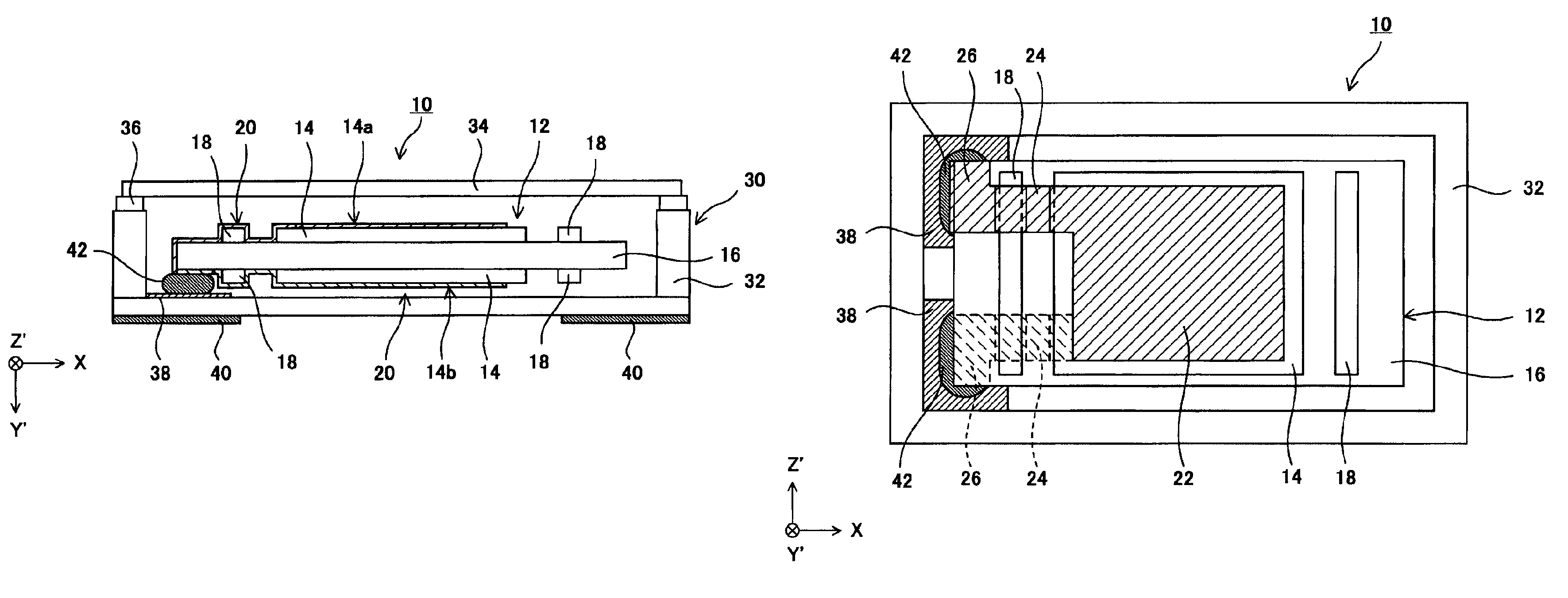
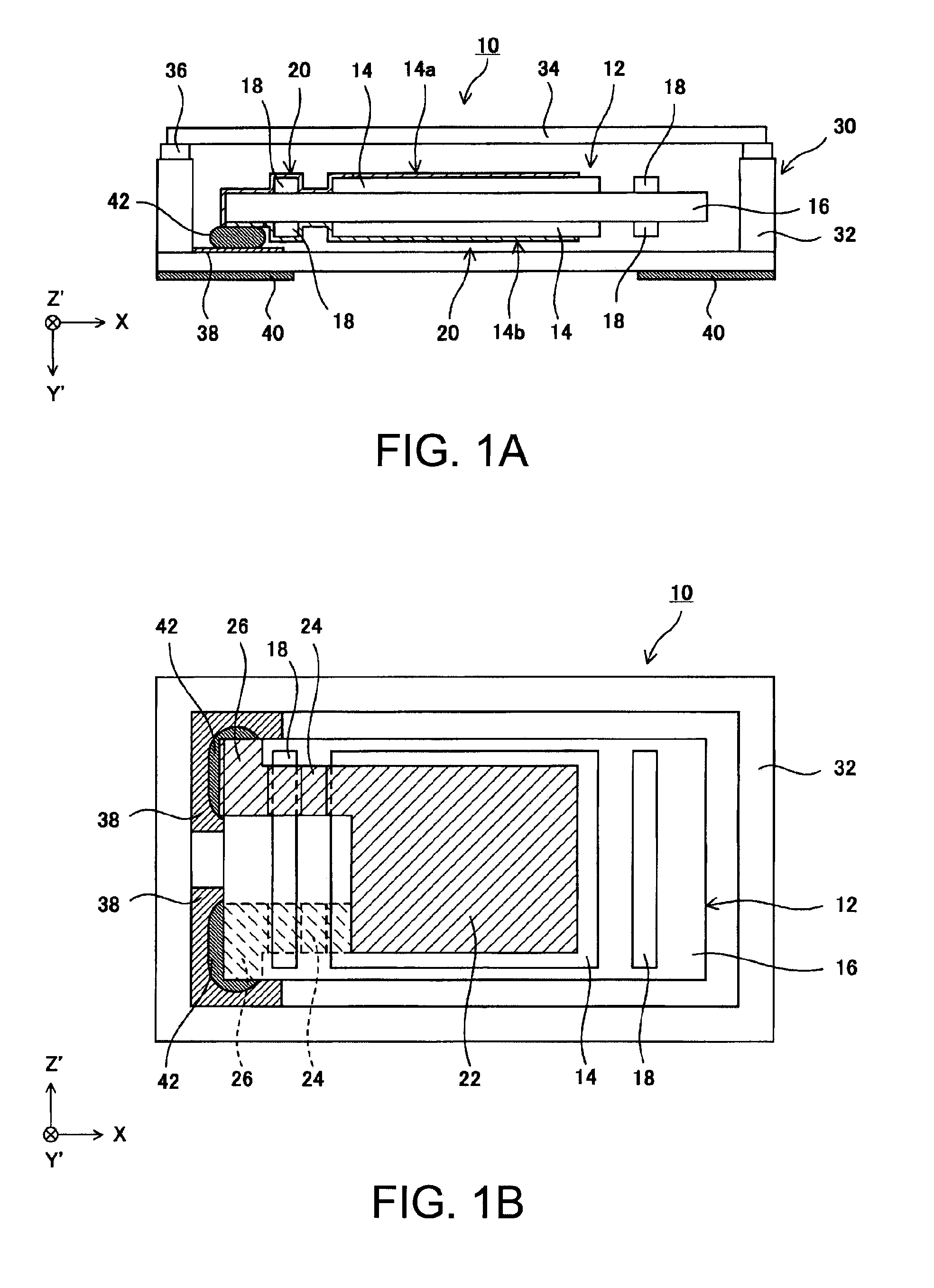
[0039]Hereinafter, a piezoelectric resonator according to an embodiment of the invention will be described in detail with reference to the accompanying drawings. First, a piezoelectric resonator according to a first embodiment of the invention will be described with reference to FIGS. 1A and 1B. In addition, FIG. 1A is a view showing the configuration of a piezoelectric resonator when viewed from the front side, and FIG. 1B is a view showing the planar configuration in a state where a lid is removed.

[0040]A piezoelectric resonator 10 according to the present embodiment includes a piezoelectric vibrating element 12 and a package 30 as main components. The piezoelectric vibrating element 12 is formed by a quartz crystal plate (piezoelectric plate) which is cut at a cut angle called AT cut or BT cut and which is excited by thickness-shear vibration as main vibration. Moreover, in the quartz crystal plate (piezoelectric vibrating element 12), a side parallel to the X axis of the quartz ...


PUM


Abstract

A vibrating element includes: an element plate that has a vibrating portion that performs thickness-shear vibration, a peripheral portion that is integrally formed with the vibrating portion, and a protruding portion that is provided at the peripheral portion; and an excitation electrode that is provided at the vibrating portion. When a side length of the vibrating portion is Mx, when a side length of the excitation electrode is Ex, and when a wavelength of flexure vibrations of the element plate is λ, the relationship of (Mx−Ex)/2=λ/2, and Mx/2={(A/2)+(¼)}λ (where, A is a positive integer) is satisfied, and when a length of the protruding portion is Dx, and when a distance between the vibrating portion and the protruding portion is Sx, the relationship of Dx=λ/2)×m, and (λ/2)×n−0.1λ≦Sx≦(λ/2)×n+0.1λ (where m and n are positive integers) is satisfied.

Description

CROSS-REFERENCE TO RELATED APPLICATIONS[0001]This is a continuation patent application of U.S. application Ser. No. 12 / 909,254 filed Oct. 21, 2010, which claims priority to Japanese Patent Application No. 2009-246902, filed Oct. 27, 2009 all of which are expressly incorporated by reference herein.BACKGROUND[0002]1. Technical Field[0003]The present invention relates to a piezoelectric resonator and in particular, to a piezoelectric resonator having a mesa type piezoelectric vibrating element in which the thickness of the vibrating portion is larger than that of the peripheral portion.[0004]2. Related Art[0005]A mesa type piezoelectric vibrating element is known as a form of a piezoelectric vibrating element which can keep vibration energy therein and which has high productivity, the form being based on a bevel or convex type piezoelectric vibrating element.[0006]In the mesa type piezoelectric vibrating element which has a level difference on the boundary of the vibrating portion and ...

Claims


Application Information

Patent Timeline
IPC IPC(8): H01L41/08H01L41/09H01L41/18H01L41/22H01L41/23H01L41/29H03H9/19
CPCH01L41/08H03H9/1021H03H9/19H10N30/00
Inventor YAMASHITA, GOKOMINE, KENJIMURAKAMI, SHIRO
Owner SEIKO EPSON CORP
Why Eureka
Try Eureka