Horizontal-flow hydration apparatus

a hydration apparatus and horizontal flow technology, applied in the direction of mixers, rotary stirring mixers, transportation and packaging, etc., can solve the problems of deterioration of pre-mix gels of hydratable polymers, problems such as problems in mixing dry additives (including hydratable polymers) with water or other aqueous fluids, and achieve rapid hydration of polymers, reduce fluid channeling, and eliminate stagnant fluid in compartments

Inactive Publication Date: 2014-02-04
MCINTIRE WILLIAM RAY
View PDF35 Cites 15 Cited by
  • Summary
  • Abstract
  • Description
  • Claims
  • Application Information

AI Technical Summary

Benefits of technology

[0032](c) at least one compartment being equipped with one or more radial-flow impellers connected to a vertical shaft, and means for rotating such impellers at a rate designed to stir the contents of the compartment radially with high shear and prevent fluid stagnation,
[0038]The apparatus subjects the aqueous fluids containing hydratable polymers to zones of high-shear mixing and zones of vertical axial flow. This promotes rapid hydration of the polymer, and helps eliminate stagnant fluid in the compartments. The full volume of the tank can thus be used effectively. The process also reduces channeling of fluids through the tank and helps reduce differences in residence times.

Problems solved by technology

Previous commercial mixing procedures encountered various problems.
Mixing dry additives (including hydratable polymers) with water or other aqueous fluids is problematic and special equipment and operating procedures are generally required to avoid chemical dusting, uneven mixing, lumping or gels.
Furthermore, with respect to batch-mix operations, job delays can result in the deterioration of pre-mix gels of the hydratable polymers, especially guar and guar derivatives, and the potential loss of the time and materials incurred in preparing the gels.
Batch operations also suffer chemical losses due to tank bottoms and costs associated with pre-treatment and post-treatment tank clean-up.
This can be a problem when attempting to hydrate polymers such as guar and HPG, even in the PCM Process of McIntire.
As Allen states, if the fluid is not managed properly, parts of the tank will become gelled and motionless and will be difficult to get moving again.
If the base fluid has not progressed sufficiently in the hydration process before the liquid is crosslinked, the fluid will have decreased viscosity and may experience stability problems.
The hydration process requires time.
Size and weight restrictions place critical limitations on equipment design.
Fluids used for oil and gas well fracturing treatments (“fracturing fluids”) made from polymers suspended in water, have distinct rheological characteristics which make achieving FIFO conditions in a large tank essentially impossible.
This tends to slow the fluid further and stabilize stagnated regions of the tank.
Different residence times for fluids is a problem particularly at start-up times. Young, partially hydrated fluid entering a tank of older, more hydrated fluid will have a lower viscosity and will tend to stay segregated from the more viscous fluid.
This is particularly problematic when the tank contains fully hydrated fluid before a fracturing treatment begins or when the fracturing treatment has been stopped for a period of time and restarted.
Without adequate control of the fluid flow, larger tank volumes are required to ensure adequate residence time for all the fluid, and even this may not be adequate if portions of the fluid are stagnant.
The resulting delay in response to rate changes makes level control difficult.
In the case of a brief inlet supply interruption, it is difficult to “catch up” by increasing the inlet rate to a vertical-flow compartmentalized tank.
This reduces the effective volume of the tank for high rates at which lower residence time exists, and reduces that residence time further.
Lastly, there is no natural flow path between pairs of compartments in such vertical-flow tanks.
This adds mechanical and operational complexity.
This leads to several problems: Large eddies are formed, thick fluid stagnates in portions of the tank, and less-hydrated fluid from the inlet channels through the tank to the discharge.
The lack of high shear mixing to accelerate hydration kinetics results in poor hydration unit performance of these horizontal-flow compartmentalized hydration units, especially at polymer concentrations normally required in hydraulic fracturing fluids.

Method used


Image

  • Horizontal-flow hydration apparatus
  • Horizontal-flow hydration apparatus
  • Horizontal-flow hydration apparatus

Examples


Embodiment Construction

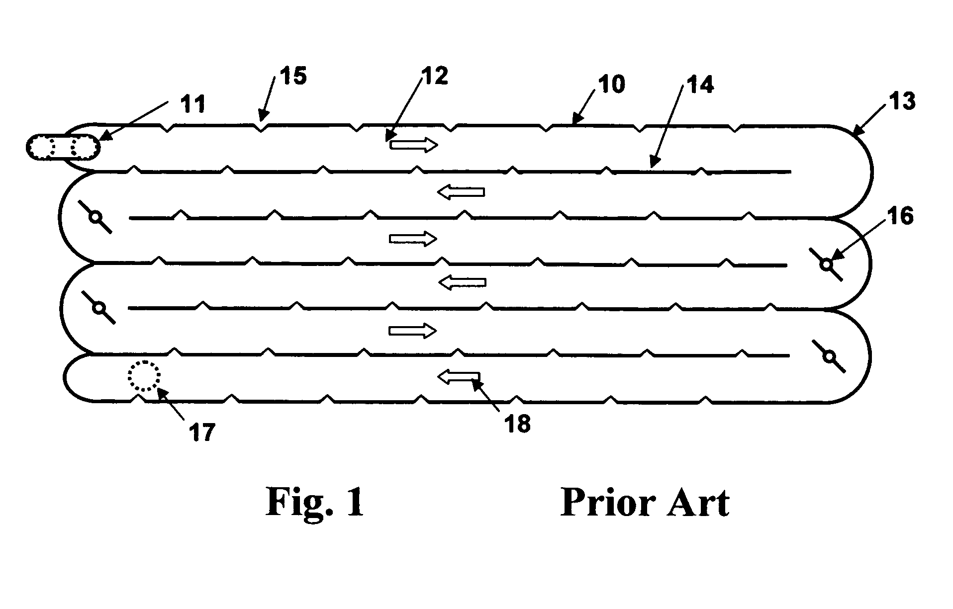
[0049]FIG. 1 illustrates a prior art horizontal-flow hydration tank 10. The tank is mounted on a trailer (not shown) to provide mobility for treating oil and gas wells. On one side of the trailer is a suction manifold leading to a centrifugal pump (not shown) that pumps water from frac tanks to the hydration tank through inlet pipe 11. Polymer powder slurried in diesel or other oil is injected into the water stream just upstream of the centrifugal pump. Turbulence in the pump and in piping between the pump and the hydration tank disperses the polymer slurry into the water stream. Water into which slurried polymer has been dispersed is pumped into the hydration tank through an inlet pipe 11 at the beginning of a long serpentine path through the tank. The hydration tank is divided into seven (7) long flow channels 12 from the top of the tank to the bottom that extend the entire length of the tank. Arrows 18 on the figure indicate the direction of fluid flow along the channels. Semicir...


PUM

PropertyMeasurementUnit
lengthaaaaaaaaaa
lengthaaaaaaaaaa
lengthaaaaaaaaaa

Abstract

A novel apparatus is disclosed which comprises:(a) pumping means for injecting a fluid through a conduit means into an inlet pipe of a fluid mixing tank,(b) said fluid mixing tank comprising a plurality of compartments connected in series and in fluid communication with adjacent compartments in the series, and designed to provide for a horizontal flow of fluids from the first compartment to the last compartment in the series,(c) at least one compartment being equipped with one or more radial-flow impellers connected to a vertical shaft, and means for rotating such impellers at a rate designed to stir the contents of the compartment radially with high shear and prevent fluid stagnation,(d) at least one compartment being equipped with one or more axial flow impellers connected to a vertical shaft, and means for rotating such impellers at a rate designed to circulate the contents of the compartment vertically,(e) the inlet pipe being designed to introduce fluids into the first compartment, and(f) a means for withdrawing fluid from the apparatus through a discharge opening in the last compartment in the series.The new apparatus is particularly useful as a horizontal flow hydration tank to prepare aqueous viscous fluids for use as well treatment fluids. Hydratable polymers can be hydrated rapidly and consistently in real time. The apparatus is less complex mechanically and operationally than the compartmentalized vertical-flow tanks of the prior art, and it can be constructed as a mobile unit.

Description

CROSS-REFERENCE TO RELATED APPLICATIONS[0001]Not ApplicableSTATEMENT REGARDING FEDERALLY FUNDED RESEARCH AND DEVELOPMENT[0002]Not Applicable.INCORPORATION BY REFERENCE OF MATERIAL SUBMITTED ON A COMPACT DISC[0003]Not applicable.BACKGROUND OF THE INVENTION[0004]1. Field of the Invention[0005]This invention relates generally to a horizontal-flow hydration apparatus and a method of using such equipment to make hydrated polymers and viscous aqueous fluids containing such hydrated polymers. Such viscous fluids are widely used in the oilfield service industry as a primary component in fracturing fluids, acidizing fluids and gravel packing fluids. The invention is particularly useful in making hydrated viscous fluids in a continuous-mix process for fracturing fluids.[0006]2. Description of Related Art[0007]The oilfield service industry uses viscous fluids extensively in treating subterranean earth formations to stimulate the production of oil and gas (i.e., natural gas) from the formation....

Claims


Application Information

Patent Timeline
Patent Type & Authority Patents(United States)
IPC IPC(8): B01F15/02B01F7/00
CPCB01F3/1221B01F13/1027B01F7/1675B01F3/1228B01F7/18B01F7/00466B01F23/54B01F23/53B01F27/1152B01F27/86B01F27/90B01F33/821
Inventor MCINTIRE, WILLIAM, RAY
Owner MCINTIRE WILLIAM RAY
Why Eureka
Try Eureka