
Microfabricated microphone

a micro-fabricated microphone and microphone technology, applied in the field of micro-fabricated microphones, can solve the problems of residual stress in the diaphragm, buckling of the diaphragm with increasing compressive stress, and approximating its fundamental physical size limit, so as to maintain the radial and angular symmetry of the diaphragm structure, reduce the negative effects of residual stress, and reduce the effect of residual stress

Inactive Publication Date: 2014-02-04
CASE WESTERN RESERVE UNIV
View PDF5 Cites 6 Cited by
  • Summary
  • Abstract
  • Description
  • Claims
  • Application Information

AI Technical Summary

Benefits of technology

The present invention is about a microído needle that reduces stress on its part that detects sound. It uses a thin layer of silicon to make a sensing diaphragm, which is attached to a supporting beam and a back-plate. This design helps to maintain the shape of the diaphragm and improves its performance in various environments.

Problems solved by technology

Even though the sizes of conventional ECMs have been reduced substantially (e.g., 4×1.5 mm), it is approaching its fundamental physical size limit.
Residual stress in the sensing diaphragm can dominate the diaphragm's mechanical performance and, for example, reduce sensitivity with increasing residual tensile stress or lead to undesirable buckling of the diaphragm with increasing compressive stress.
Thus, residual stress in the diaphragm can negatively affect a microfabricated microphone's sensibility, noise, and over-pressure response.
However, controlling residual stress requires very tight process control for consistent stress.
However, the arm connected at a portion of the edge introduces radial and angular asymmetry in the sensing diaphragm structure, and as a result asymmetry in the stress relaxation.
Therefore, even though free plate scheme may mitigate some residual stress in the sensing diaphragm, there are still performance limits and complications in its manufacturing process.

Method used


Image

  • Microfabricated microphone
  • Microfabricated microphone
  • Microfabricated microphone

Examples


Embodiment Construction

[0024]The various aspects of the subject innovation are now described with reference to the annexed block diagrams and drawings, wherein like numerals refer to like or corresponding elements throughout. It should be understood, however, that the block diagrams, drawings and detailed description relating thereto are not intended to limit the claimed subject matter to the particular form disclosed. Rather, the intention is to cover all modifications, equivalents, and alternatives falling within the spirit and scope of the claimed subject matter.

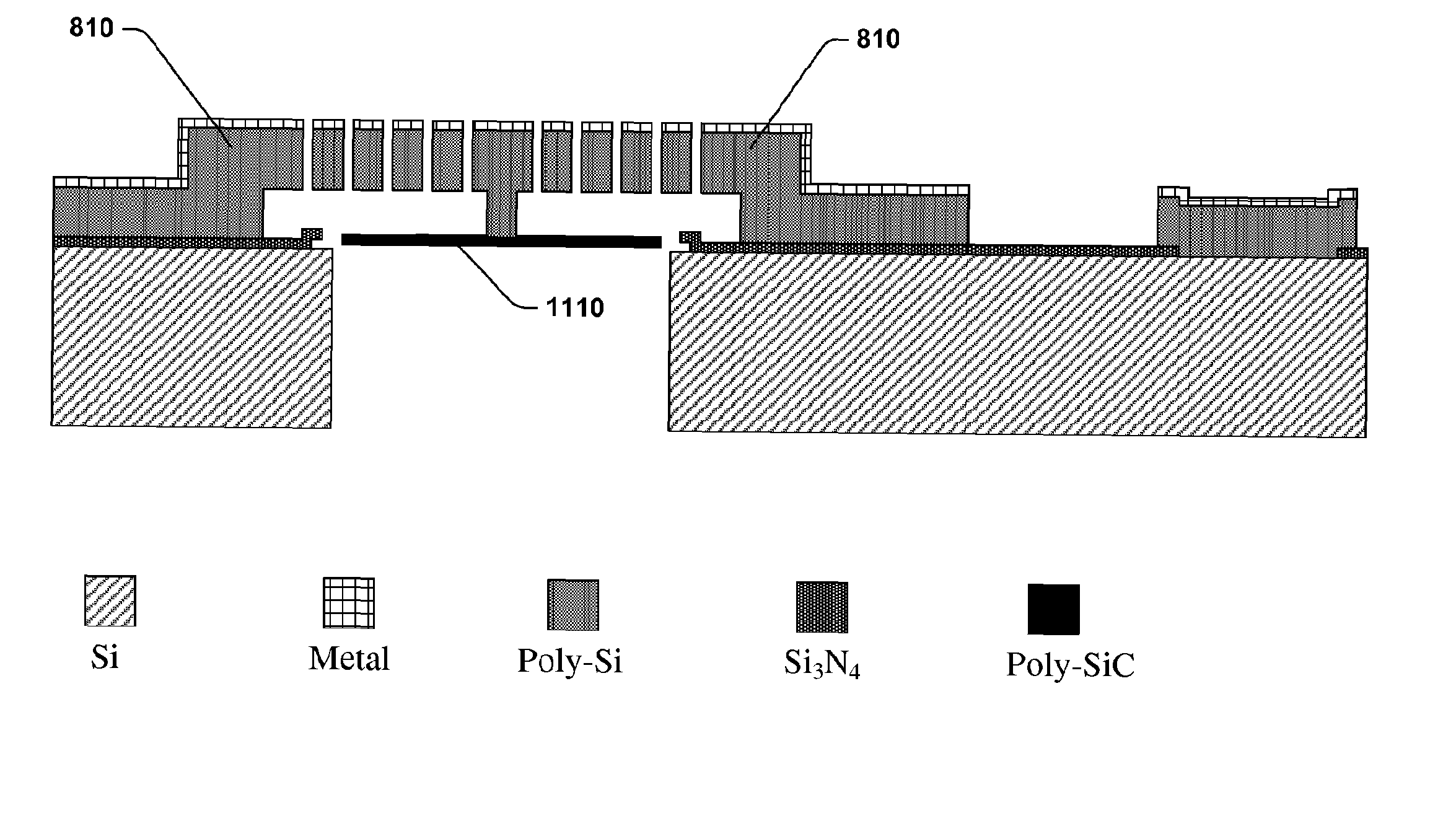
[0025]The present invention provides a microfabricated microphone. The microphone consists of a center-supported diaphragm to mitigate negative effects of residual stress. In particular, the diaphragm can be anchored at its center allowing the residual stress to relax through radial contraction or expansion of the diaphragm. The diaphragm can consist of a single circular plate made from a thinner, bottom layer poly-silicon. The diaphragm can be...


PUM


Abstract

The present invention provides a microfabricated microphone that can mitigate negative effects caused by residual stress in its sensing diaphragm. In particular, a center-supported diaphragm is provided to allow residual stress to relax through the radial expansion or contraction of the diaphragm. The diaphragm is suspended by an anchor that is attached to a supporting beam. The supporting beam is situated in between one or more sections of a back-plate electrode. The supporting beam is mechanically and electrically separated from the back-plate electrode. Various mechanical dimensions of the aforementioned components are also disclosed to optimize performance of a microfabricated microphone in different operational conditions. Further, a method and system for fabricating a microfabricated microphone with a center-supported diaphragm is also disclosed.

Description

CROSS REFERENCE TO RELATED APPLICATIONS[0001]This application corresponds to PCT / US08 / 054,302, filed Feb. 19, 2008, which claims the benefit of U.S. Provisional Application No. 60 / 890,762, filed Feb. 20, 2007, which is herein incorporated by reference it its entirety.TECHNICAL FIELD[0002]The present invention relates generally to microfabricated microphones and, in particular, to a microfabricated microphone that consists of a center-supported diaphragm that mitigates residual stress.BACKGROUND[0003]New and more powerful electronic devices and computers are continually developed (e.g., digital audio players, video players, cell phones, personal digital assistants). As more new features are added into electronic devices and computers, there continues to be pressure in integrating and reducing the size of components within electronic devices. Particularly, the acoustic input components of electronic devices and computers are also subject to this size-reducing pressure. A conventional ...

Claims


Application Information

Patent Timeline
Patent Type & Authority Patents(United States)
IPC IPC(8): H04R25/00
CPCH04R31/00H04R19/005
Inventor MEHREGANY, MEHRAN
Owner CASE WESTERN RESERVE UNIV
Learn More