Structural frame for a turbomachine

a structure frame and turbomachine technology, applied in the direction of machines/engines, machine supports, liquid fuel engines, etc., can solve the problems of complicated structural frame types, complicated maintenance operations of turbomachine, and long and complex machining operations, so as to achieve simple, effective and convenient maintenance.

Active Publication Date: 2014-02-11
SN DETUDE & DE CONSTR DE MOTEURS DAVIATION S N E C M A
View PDF16 Cites 11 Cited by
  • Summary
  • Abstract
  • Description
  • Claims
  • Application Information

AI Technical Summary

Benefits of technology

[0008]A particular object of the invention is to avoid those dr

Problems solved by technology

Nevertheless, making that type of structural frame becomes increasingly complicated and expensive with increasing diameter of the frame.
Furthermore, after casting, lengthy and complex machining operations need to be performed on the outer ring where it has jun

Method used


Image

  • Structural frame for a turbomachine
  • Structural frame for a turbomachine
  • Structural frame for a turbomachine

Examples


Embodiment Construction

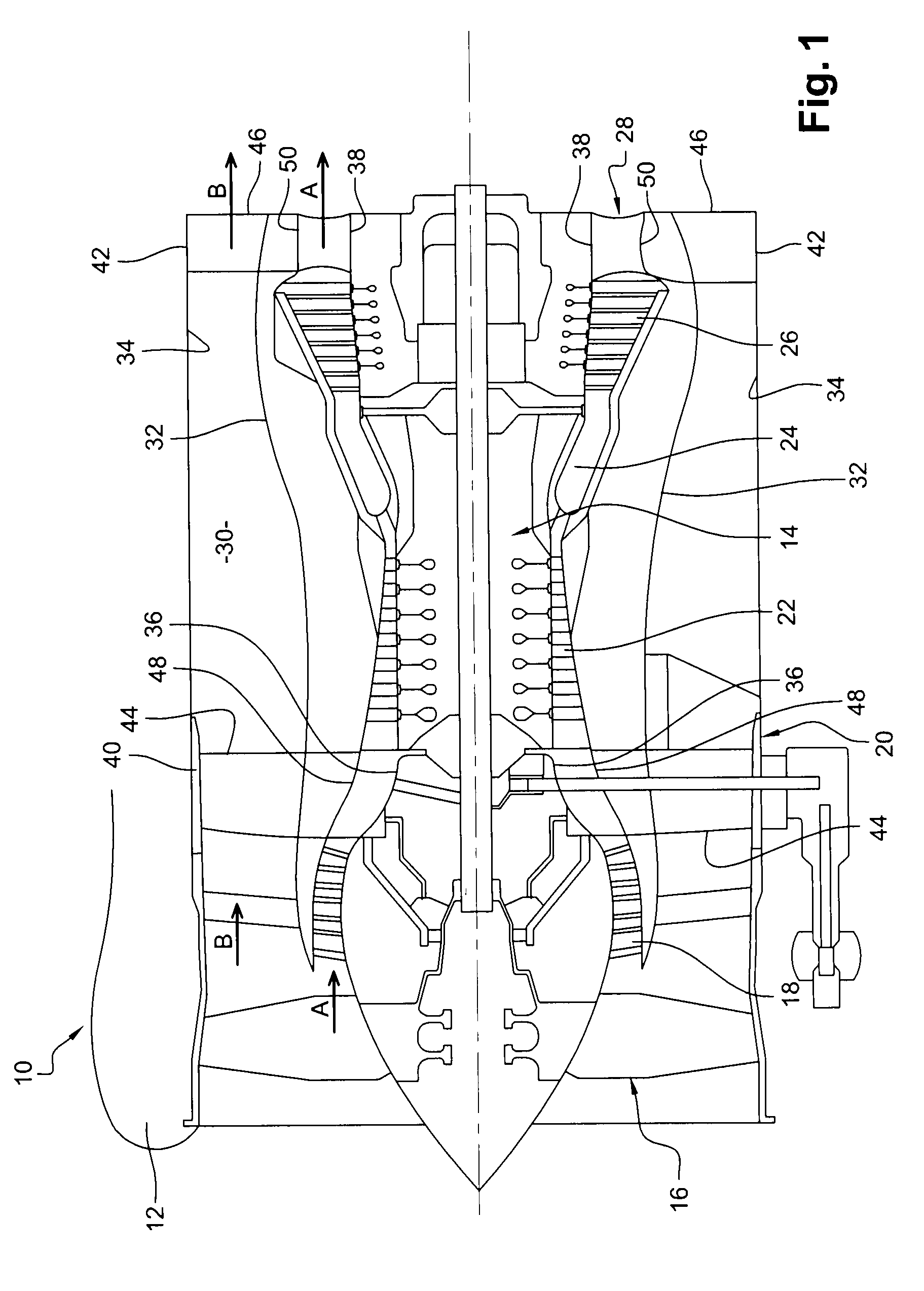
[0029]FIG. 1 shows a bypass turbomachine 10 comprising nacelle 12 of cylindrical shape surrounding a turbojet 14 and a fan wheel 16 mounted upstream from the turbojet 14, which turbojet essentially comprises, from upstream to downstream: a low pressure compressor 18, an intermediate frame 20, a high pressure compressor 22, a combustion chamber 24, a turbine 26, and an exhaust frame 28.

[0030]In operation, the fan wheel 16 driven by the turbine 26 sucks in a stream of air that divides into a primary air stream (arrows A) that passes through the turbojet 14, and a secondary air stream (arrows B) that flows along a fan duct 30 inside the nacelle 12 towards the rear and around the turbojet 14.

[0031]The fan duct 30 is made up of two substantially cylindrical walls that are coaxial, respectively an inner wall 32 and an outer wall 34.

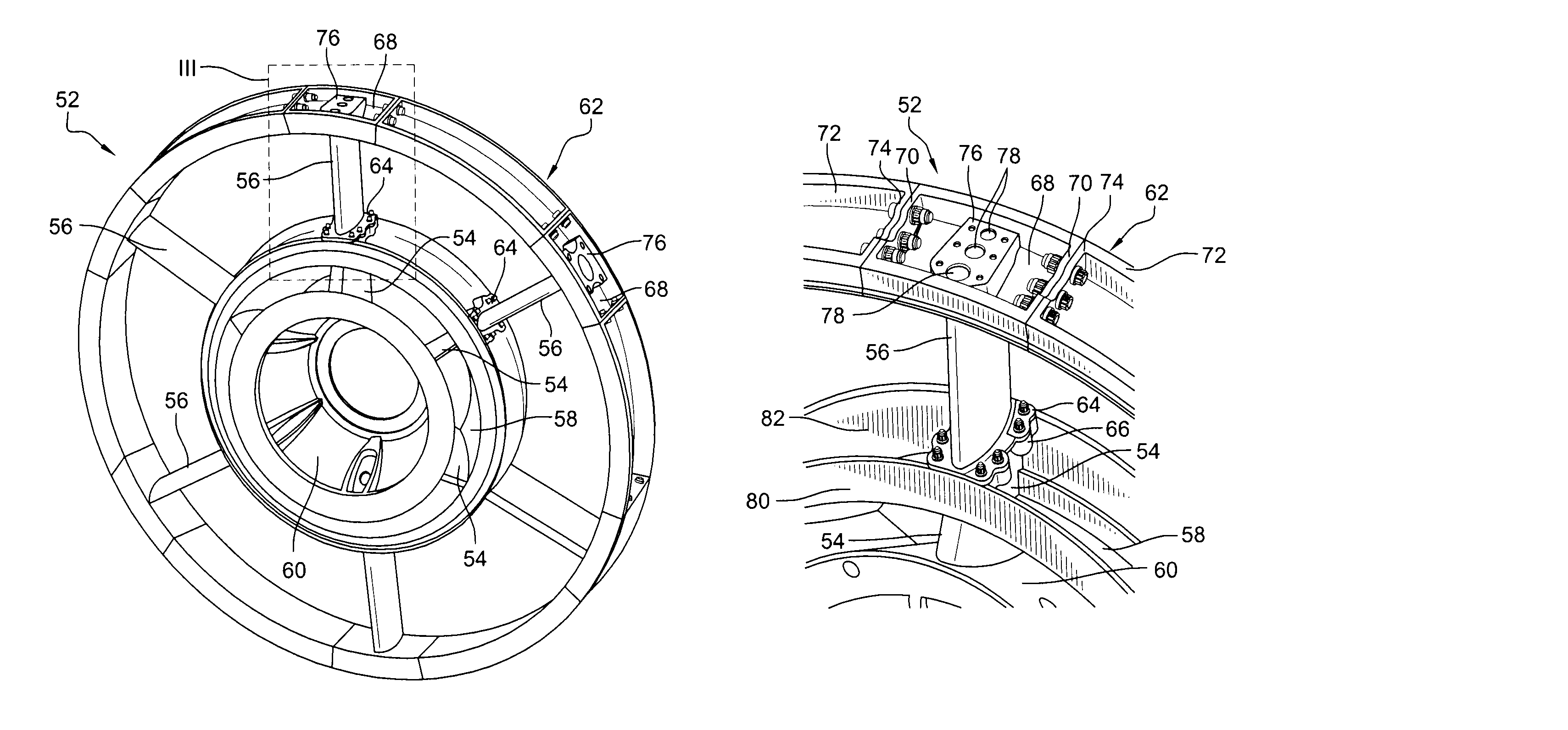
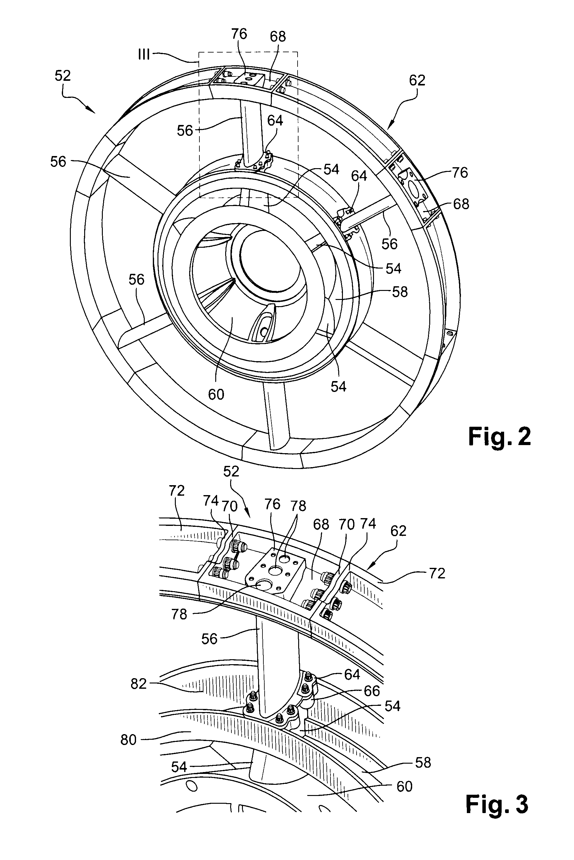
[0032]The intermediate frame 20 and the exhaust frame 28 are structural frames serving to stiffen the turbomachine in order to limit distortion thereof in oper...


PUM


Abstract

A structural frame for a turbomachine, such as an intermediate frame or an exhaust frame, the frame including at least two coaxial rings, an inner ring and an outer ring, together with radial arms interconnecting the rings. At least one of these elements includes a plurality of parts that are fastened together by bolting.

Description

BACKGROUND OF THE INVENTION[0001]1. Field of the Invention[0002]The invention relates to a structural frame for a turbomachine, such as in particular a fan frame, an intermediate frame, or an exhaust frame, and it also relates to a turbomachine including a frame of this type.[0003]2. Description of the Related Art[0004]In a turbomachine, such as an airplane turbojet, structural frames are arranged along the drive axis in order to stiffen the turbomachine, in order to avoid distortion of the turbomachine, and thereby transmit thrust forces better to the airplane to which the turbomachine is fastened. By way of example, such structural frames are the intermediate frame and the exhaust frame. The intermediate frame is situated between the low and high pressure compressors, and the exhaust frame is located downstream from a turbine section arranged at the outlet from a combustion chamber.[0005]This type of frame is generally made up at least two coaxial rings, an inner and an outer ring...

Claims


Application Information

Patent Timeline
IPC IPC(8): F16M1/00F16M7/00F16M9/00F04D29/54F04D29/44F16M3/00F02C7/20F16M5/00
CPCF01D25/243F05D2230/60F01D25/246F01D9/04Y02T50/672Y02T50/60
Inventor DUCHATELLE, THIERRY FRANCOIS MAURICEPAPIN, THIERRY GEORGES PAULRAULIN, DOMINIQUESANCHEZ, ARNAUD
Owner SN DETUDE & DE CONSTR DE MOTEURS DAVIATION S N E C M A
Why Eureka
Try Eureka