Bioinformation acquisition apparatus

a bioinformation acquisition and apparatus technology, applied in the field of light-emitting bioinformation acquisition apparatuses, can solve the problems of reducing the strength of the acoustic wave signal coming from a deep portion of a living body, high cost of pulsed light source generators, and high cost of optical energy of light flux, so as to improve the use efficiency of radiated light

Inactive Publication Date: 2014-02-11
CANON KK
View PDF21 Cites 18 Cited by
  • Summary
  • Abstract
  • Description
  • Claims
  • Application Information

AI Technical Summary

Benefits of technology

[0008]The bioinformation imaging apparatus of a conventional example described above using photoacoustic effect can acquire a stronger acoustical wave signal by applying a large amount of optical energy to a living body.
[0010]Therefore, to enhance observation capability in a deep portion of a living body, it is desirable to use optical energy more efficiently.
[0012]That is, a flux of light radiated into a living body loses straightness due to strong diffusion in the living body, and a part of the light flux is radiated from an irradiation area and adjacent areas outside the body due to backscattering. By reusing this emitted flux, it can be expected to enhance the strength of a signal.
[0014]An objective of the present invention, in terms of the aforementioned problems, is to provide a bioinformation acquisition apparatus which can reuse a flux of light emitted from a test object due to diffusion in the test object when the test object is irradiated with light, and can enhance use efficiency of the radiated light.
[0017]According to the present invention, a flux of light emitted from a test object when the test object is irradiated with light is reflected by a reflection-type polarization element and projected to the test object again, so that the flux of light emitted from the test object can be reused, improving use efficiency of the radiated light.

Problems solved by technology

However, using such photoacoustic effect has a problem in that an acoustical wave signal coming from a deep portion in a living body has a lowered strength, because the optical energy of the flux of light that has reached that deep portion has been attenuated.
Therefore, it is necessary to use a pulsed light source generator having high power as a light source to observe a deep portion of a living body, but the pulsed light source generator is limited in output and furthermore such a pulsed light source generator is expensive.
Further, there also arises a problem that as the output is made higher, it becomes unstable.

Method used


Image

  • Bioinformation acquisition apparatus
  • Bioinformation acquisition apparatus
  • Bioinformation acquisition apparatus

Examples


example 1

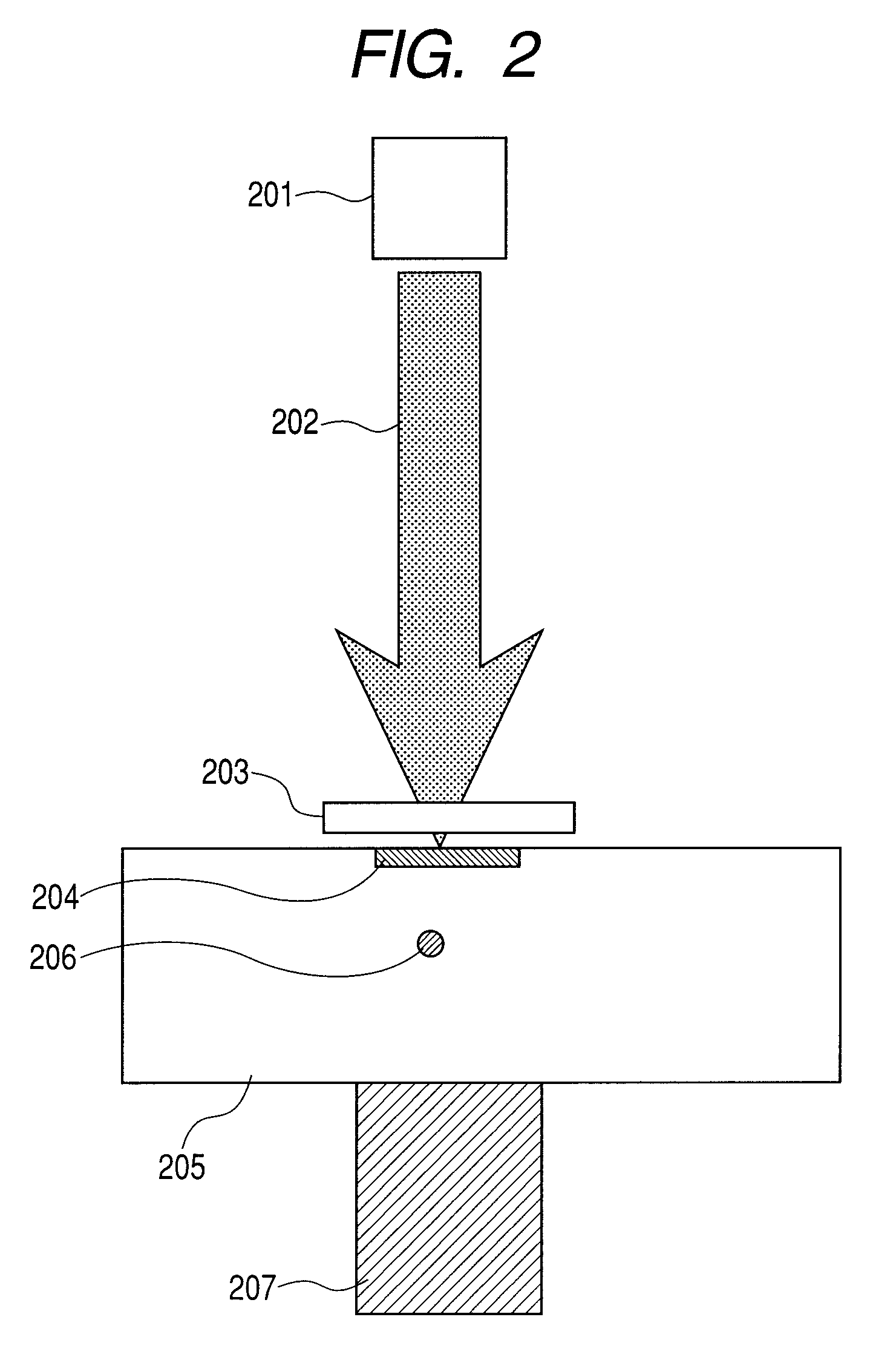
[0075]Referring to FIG. 2, an example of a configuration of a bioinformation acquisition apparatus having a reflection-type polarization element in an example 1 according to the present invention will be described. A flux of light 202 emitted by a light source 201 is directed to a phantom 205 which is a simulated living body. Here, the flux of light 202 is applied to the surface of the phantom approximately vertically thereto. A reflection-type polarization element 203 is disposed in a propagating path of the flux of light 202 and the surface of the phantom is radiated through the reflection-type polarization element 203.

[0076]As the reflection-type polarization element 203, a wire grid polarizer is used here. A polarization state of the flux of light is linear polarization of a p-polarization component and the flux of light 202 passes through the reflection type polarization element 203 without loss of its optical energy. That is, a p-polarization component of the flux of light pas...

example 2

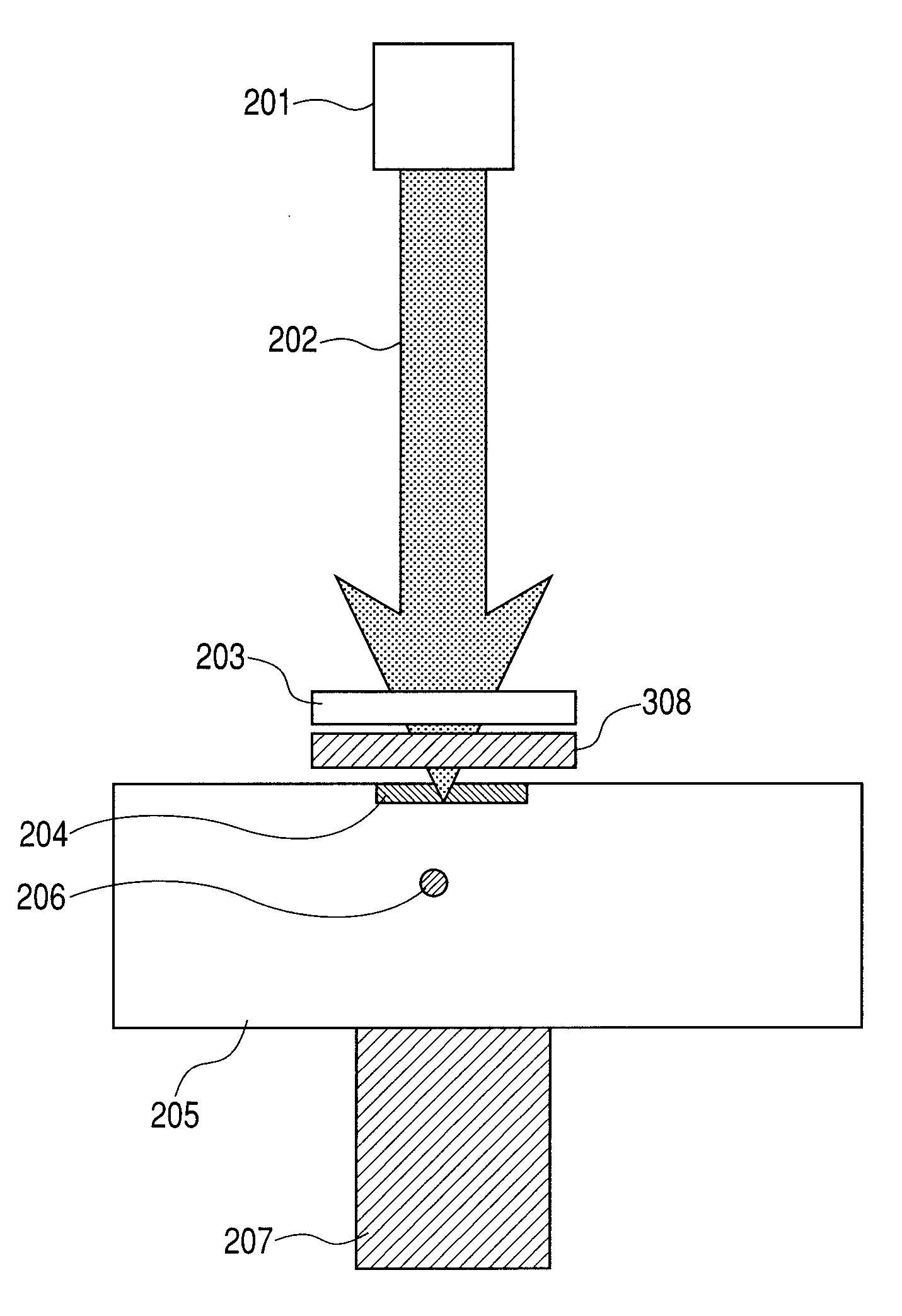
[0080]Referring to FIG. 3, an example of a configuration of a bioinformation acquisition apparatus having a reflection-type polarization element in an Example 2 according to the present invention will be described. This example basically has a like configuration as Example 1, only differing in that a λ / 4 wave plate 308 is inserted between a phantom 205 and a reflection-type polarization element 203. As described in a similar manner in the following examples, overlapping features will be omitted.

[0081]In Example 2 configured as described above, the strength of the photo-acoustical signal is intensified, the quantity of the radiated light is increased and the photo-acoustical signal is enhanced, as compared with the case without the reflection-type polarization element 203 and the λ / 4 wave plate 308.

example 3

[0082]Referring to FIG. 4, an example of a configuration of a bioinformation acquisition apparatus having a reflection-type polarization element in an Example 3 according to the present invention will be described. This example basically has a like configuration as Example 1, only differing in that a reflection-type polarization element 203 is positioned in contact with a phantom 205.

[0083]When the photo-acoustical signal is detected similarly to Example 1, the quantity of the radiated light is increased and the photo-acoustical signal is enhanced, compared with the case without the reflection-type polarization element. Also, when the reflection type polarization element 203 varied in size is used for measurement, the signal strength is considerably improved at the size thereof equal to or slightly larger than the area of the irradiation area 204.

[0084]In this example, the quantity of light applied to the irradiation area can be effectively increased, as compared with the case where...


PUM

PropertyMeasurementUnit
diameteraaaaaaaaaa
frequencyaaaaaaaaaa
lengthaaaaaaaaaa

Abstract

In a bioinformation acquisition apparatus, a flux of light emitted from a test object through diffusion when the test object is irradiated with light can be reused, improving use efficiency of the radiated light. The apparatus has a light source for irradiating the test object with the flux of light, and a detector for detecting a signal output based on the radiation, and includes: a reflection-type polarization element adapted that at least a part of the flux of light from the light source can be transmitted through, and a flux of light emitted from the test object by the radiation can be reflected, in which the reflection-type polarization element is disposed at a position opposite to an irradiation area of the light on the surface of the test object to cover the irradiation area.

Description

BACKGROUND OF THE INVENTION[0001]1. Field of the Invention[0002]The present invention relates to a bioinformation acquisition apparatus using light and in particular to technology for enhancing optical energy use efficiency by re-irradiating a living body with a flux of light that has diffused through and been emitted from a living body.[0003]2. Description of the Related Art[0004]Research and development have been done for visualizing information in a living body by using near infrared rays because infrared light is noninvasive and is transmitted well through a living body, i.e., a test object. In vivo material such as water, fat or hemoglobin present in a blood vessel has a peculiar spectrum in the near-infrared wavelength range. Much study, therefore, has directed to visualizing a spatial coefficient distribution of absorption originating from those components to acquire functional information in a living body.[0005]A method for detecting optical absorption in a living body inclu...

Claims


Application Information

Patent Timeline
Patent Type & Authority Patents(United States)
IPC IPC(8): G01N21/00G01N21/55A61B8/00G01N29/00
CPCA61B5/14542A61B5/0059
Inventor ICHIHARA, SHIGERUKOBAYASHI, SHUICHI
Owner CANON KK
Why Eureka
Try Eureka