Particle accelerators having electromechanical motors and methods of operating and manufacturing the same

a technology of electromechanical motors and accelerators, which is applied in the direction of accelerators, electric discharge tubes, electrical apparatus, etc., can solve the problems of large radiation along the interior surface, large space occupation of mechanical devices within the acceleration chamber, and difficulty in operation,

Active Publication Date: 2014-02-18
GENERAL ELECTRIC CO
View PDF9 Cites 23 Cited by
  • Summary
  • Abstract
  • Description
  • Claims
  • Application Information

AI Technical Summary

Problems solved by technology

In some cases, magnetic components in the mechanical devices may disturb the magnetic field responsible for directing the charged particles.
Furthermore, a large amount of radiation may exist along the interior surfaces that define the acceleration chamber.
In addition to the above concerns regarding the environment, mechanical devices within the acceleration chamber may require a large amount of space and be difficult to operate or may lack a high level of precision.
These motors cannot operate effectively in a high magnetic field of the acceleration chamber and can also interfere with the well-defined magnetic field therein.
However, these mechanical components and the vacuum feed increase the complexity of the particle accelerator.

Method used


Image

  • Particle accelerators having electromechanical motors and methods of operating and manufacturing the same
  • Particle accelerators having electromechanical motors and methods of operating and manufacturing the same
  • Particle accelerators having electromechanical motors and methods of operating and manufacturing the same

Examples


Embodiment Construction

[0018]As used herein, an element or step recited in the singular and proceeded with the word “a” or “an” should be understood as not excluding plural of said elements or steps, unless such exclusion is explicitly stated. Furthermore, references to “one embodiment” are not intended to be interpreted as excluding the existence of additional embodiments that also incorporate the recited features. Moreover, unless explicitly stated to the contrary, embodiments “comprising” or “having” an element or a plurality of elements having a particular property may include additional such elements not having that property.

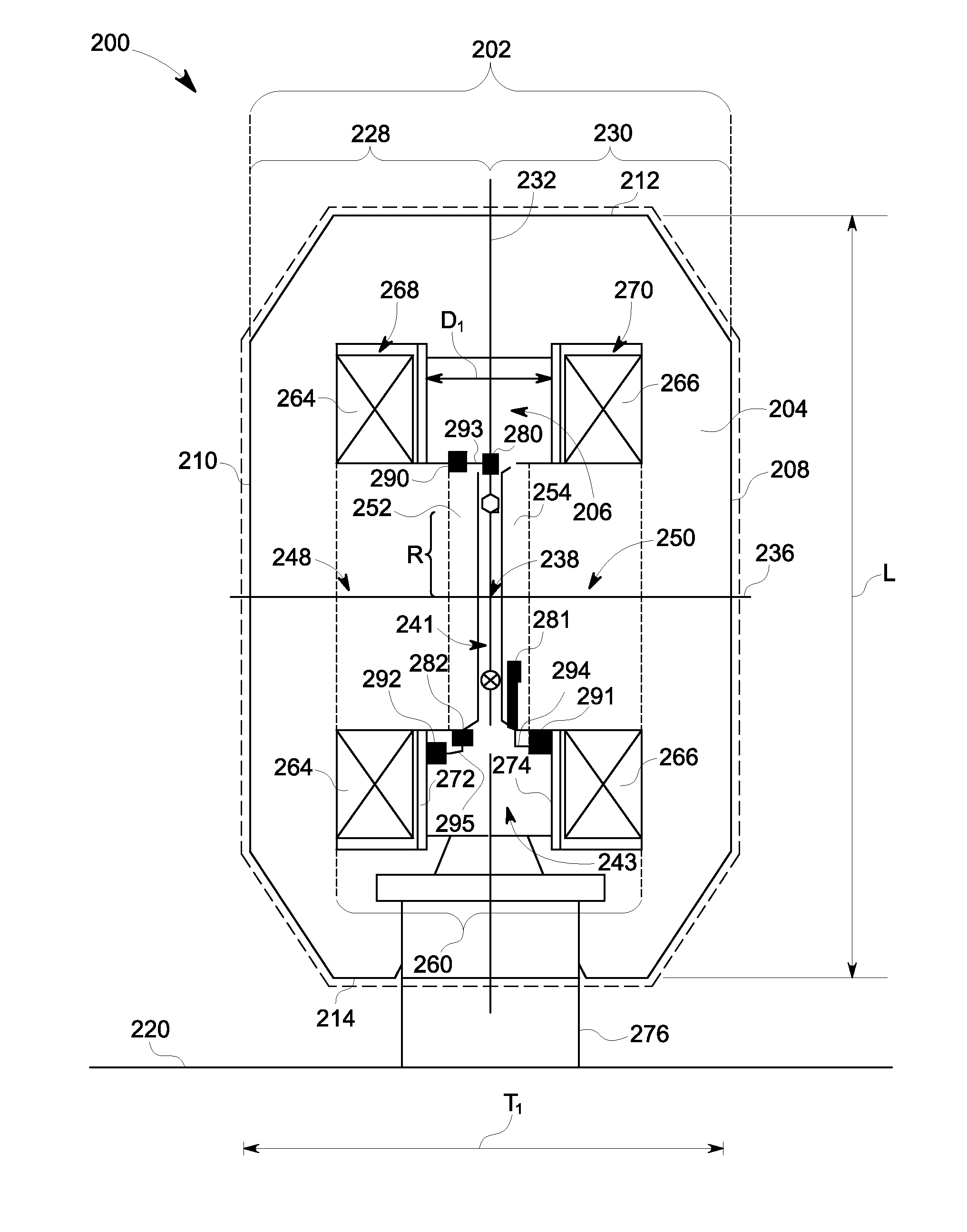
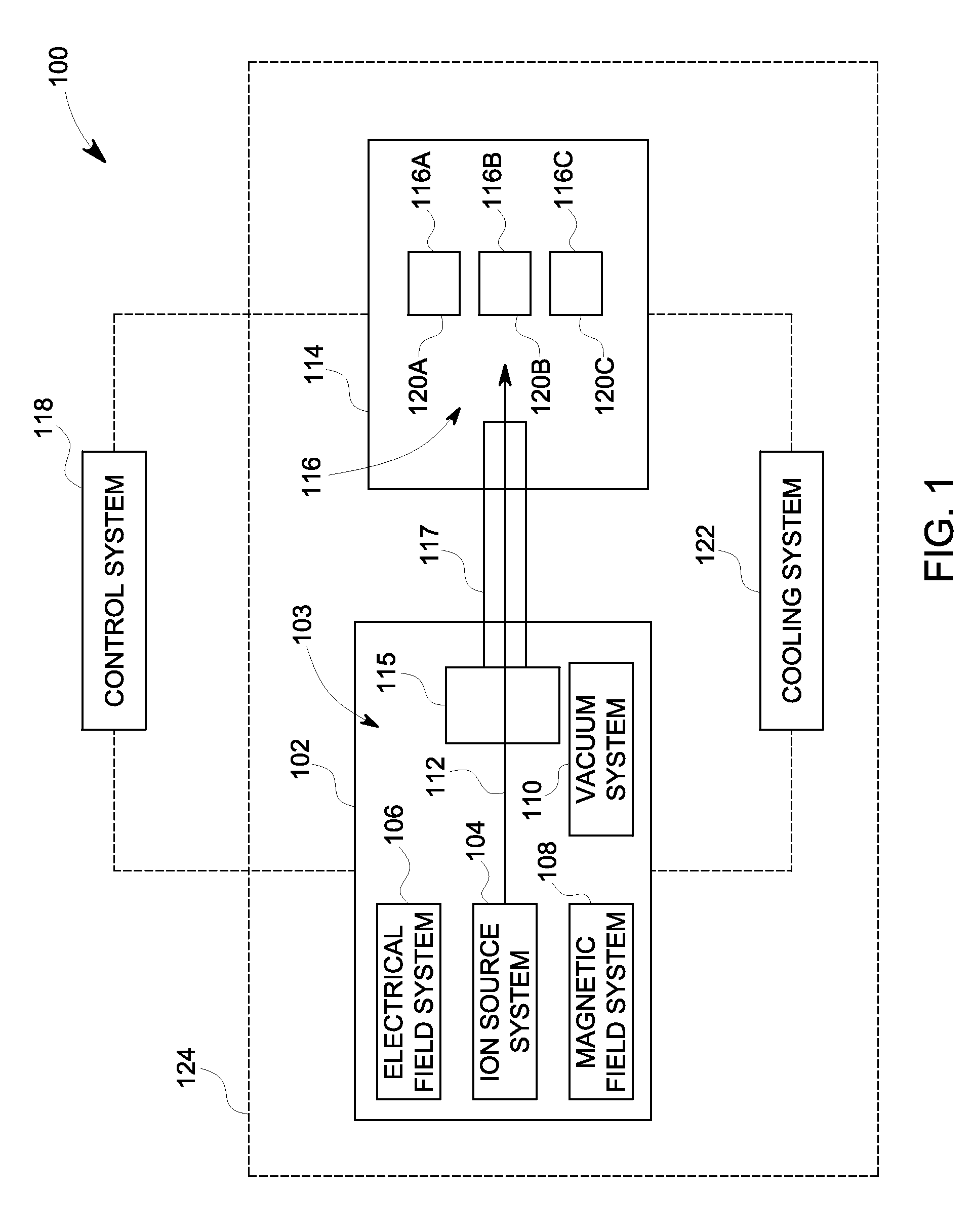
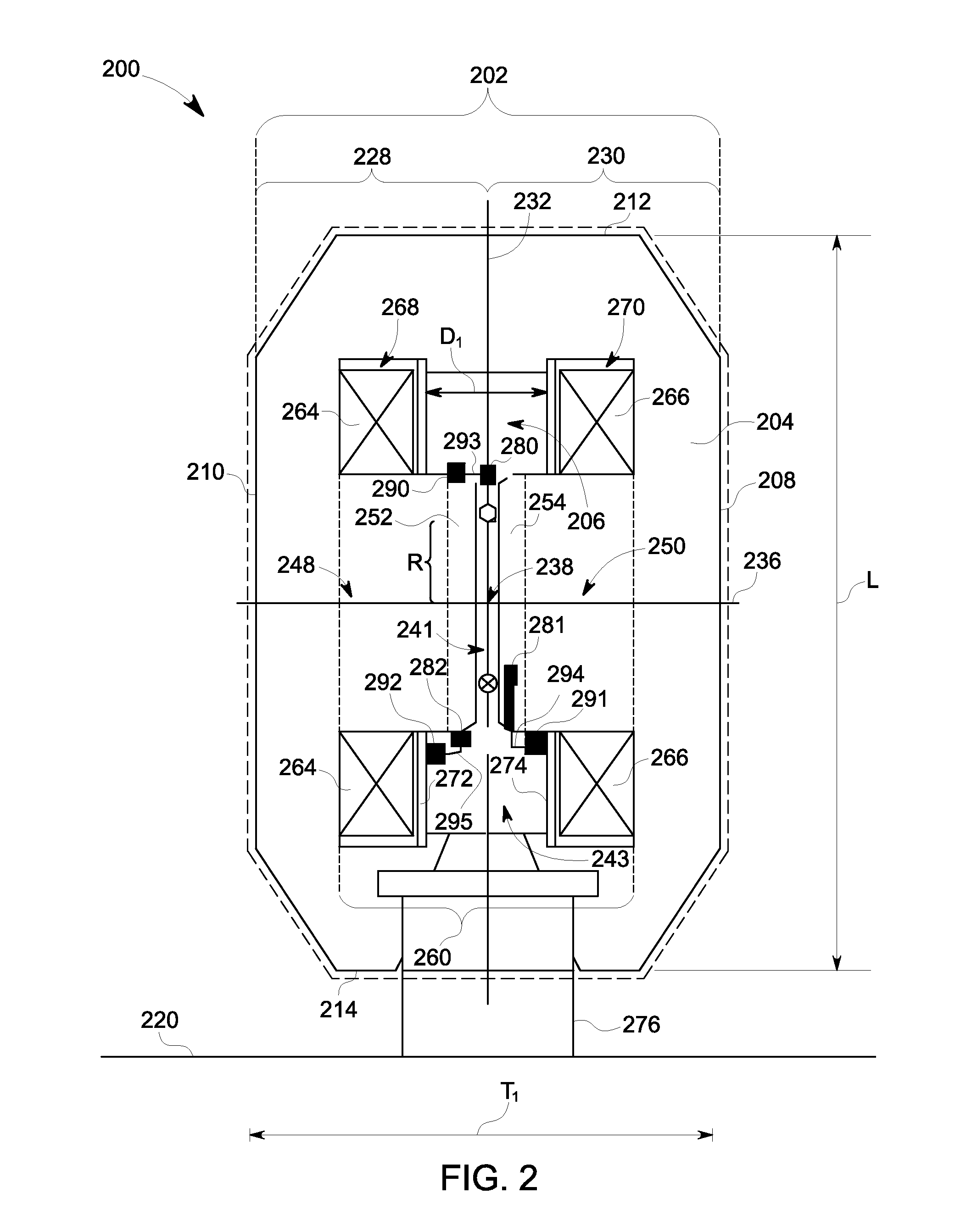
[0019]FIG. 1 is a block diagram of an isotope production system 100 formed in accordance with one embodiment. The system 100 includes a particle accelerator 102 that has several sub-systems including an ion source system 104, an electrical field system 106, a magnetic field system 108, and a vacuum system 110. The particle accelerator 102 may be, for example, a cyclotron or, more...


PUM


Abstract

A particle accelerator including an electrical field system and a magnetic field system that are configured to direct charged particles along a desired path within an acceleration chamber. The particle accelerator also includes a mechanical device that is located within the acceleration chamber. The mechanical device is configured to be selectively moved to different positions within the acceleration chamber. The particle accelerator also includes an electromechanical (EM) motor having a connector component and piezoelectric elements that are operatively coupled to the connector component. The connector component is operatively attached to the mechanical device. The EM motor drives the connector component when the piezoelectric elements are activated thereby moving the mechanical device.

Description

BACKGROUND OF THE INVENTION[0001]Embodiments of the invention described herein relate generally to particle accelerators, and more particularly to particle accelerators having moveable mechanical devices located within acceleration chambers.[0002]Particle accelerators, such as cyclotrons, may have various industrial, medical, and research applications. For example, particle accelerators may be used to produce radioisotopes (also called radionuclides), which have uses in medical therapy, imaging, and research, as well as other applications that are not medically related. Systems that produce radioisotopes typically include a cyclotron that has a magnet yoke surrounding an acceleration chamber. The cyclotron may include opposing pole tops that are spaced apart from each other. Electrical and magnetic fields may be generated within the acceleration chamber to accelerate and guide charged particles along a spiral-like orbit between the poles. To produce the radioisotopes, the cyclotron ...

Claims


Application Information

Patent Timeline
Patent Type & Authority Patents(United States)
IPC IPC(8): H05H15/00H05H7/00
CPCH05H7/00H05H2007/088H05H13/005H05H2007/125G21K5/10H02N2/0095Y10T29/49002
Inventor ERIKSSON, TOMASHOLMGREN, BERT
Owner GENERAL ELECTRIC CO
Why Eureka
Try Eureka