Dynamically reconfigurable feed network for multi-element planar array antenna

a planar array antenna and dynamic reconfiguration technology, applied in the field of communication antennas, can solve the problems of not providing the flexibility afforded by real-time reconfigurability of either parameter, and not overcoming the necessary complexity of routing bias voltages to each and every

Active Publication Date: 2014-02-18
THE UNITED STATES OF AMERICA AS REPRESETNED BY THE SEC OF THE AIR FORCE
View PDF12 Cites 17 Cited by
  • Summary
  • Abstract
  • Description
  • Claims
  • Application Information

AI Technical Summary

Benefits of technology

[0022]Briefly stated, the present invention achieves these and other objects by providing a reconfigurable feed network for antenna having a microstrip patchwork radiating surface wherein individual radiating patches and elements of a stripline feed structure can be connected to and disconnected from each other via photoconductive interconnections. Commands from software alternately turn light from light emitting sources on or off, the light or lack thereof being channeled from an underside layer of the antenna so as to enable or disable the photoconductive interconnections. The resultant connection or disconnection of the radiating patches to each other and to the stripline feed structure will vary the antenna's frequency, bandwidth, and beam pointing.

Problems solved by technology

While apparently successful in reducing array size for a given bandwidth, the fragmented aperture technique does not provide the flexibility afforded by real time reconfigurability of either parameter.
While this reference apparently provides real time control of beam steering and bandwidth with adaptability to conformal applications, the method of operation requires the physical movement of microstrip pixels into and out of alignment with the radiating elements' plane, with no disclosed means for providing such movement.
While this reference represents an advancement in the state-of-the-art of reconfigurable antennas it has not overcome the necessary complexity of routing bias voltages to each and every FET, nor the associated power consumption.

Method used


Image

  • Dynamically reconfigurable feed network for multi-element planar array antenna
  • Dynamically reconfigurable feed network for multi-element planar array antenna
  • Dynamically reconfigurable feed network for multi-element planar array antenna

Examples


Embodiment Construction

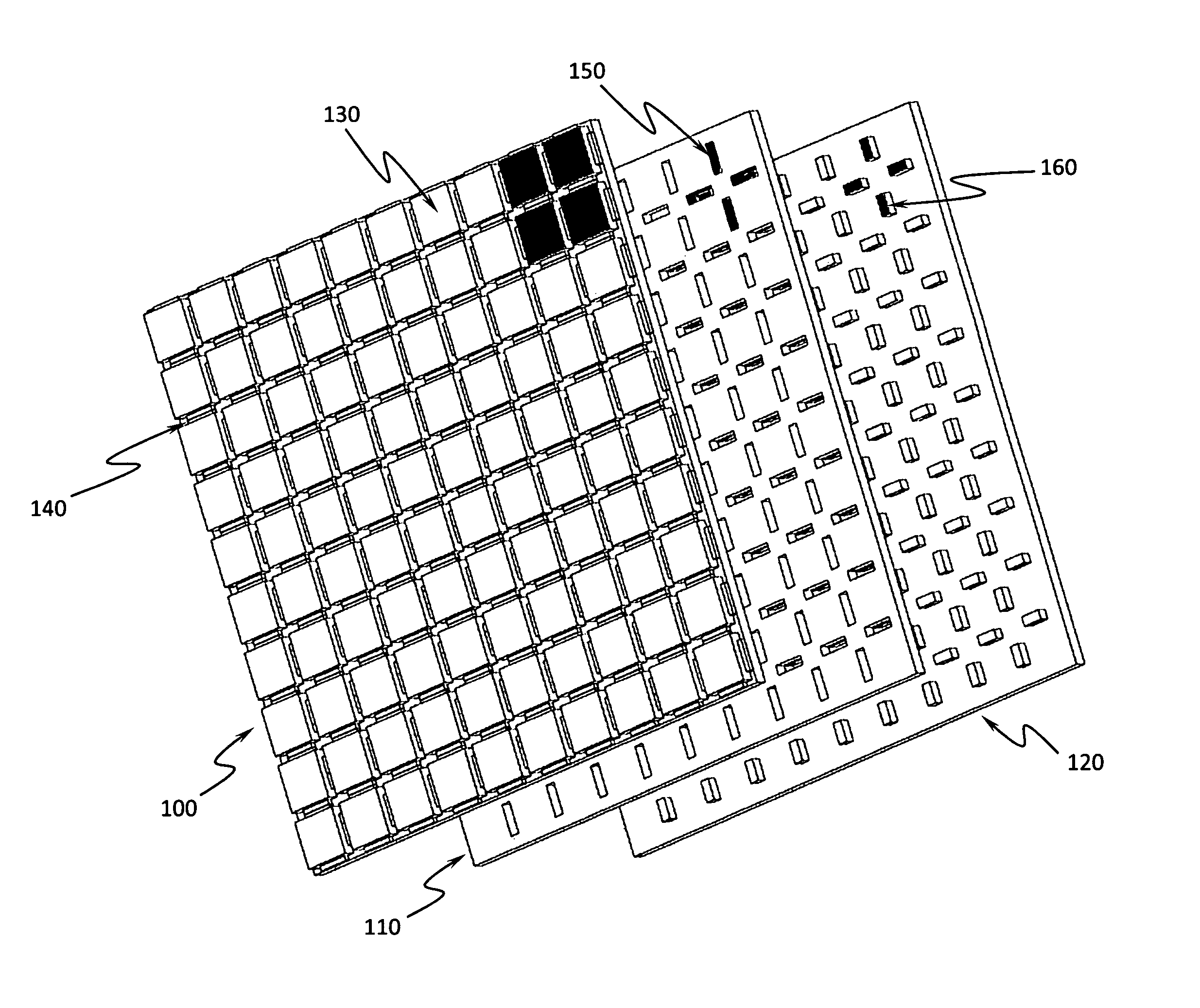
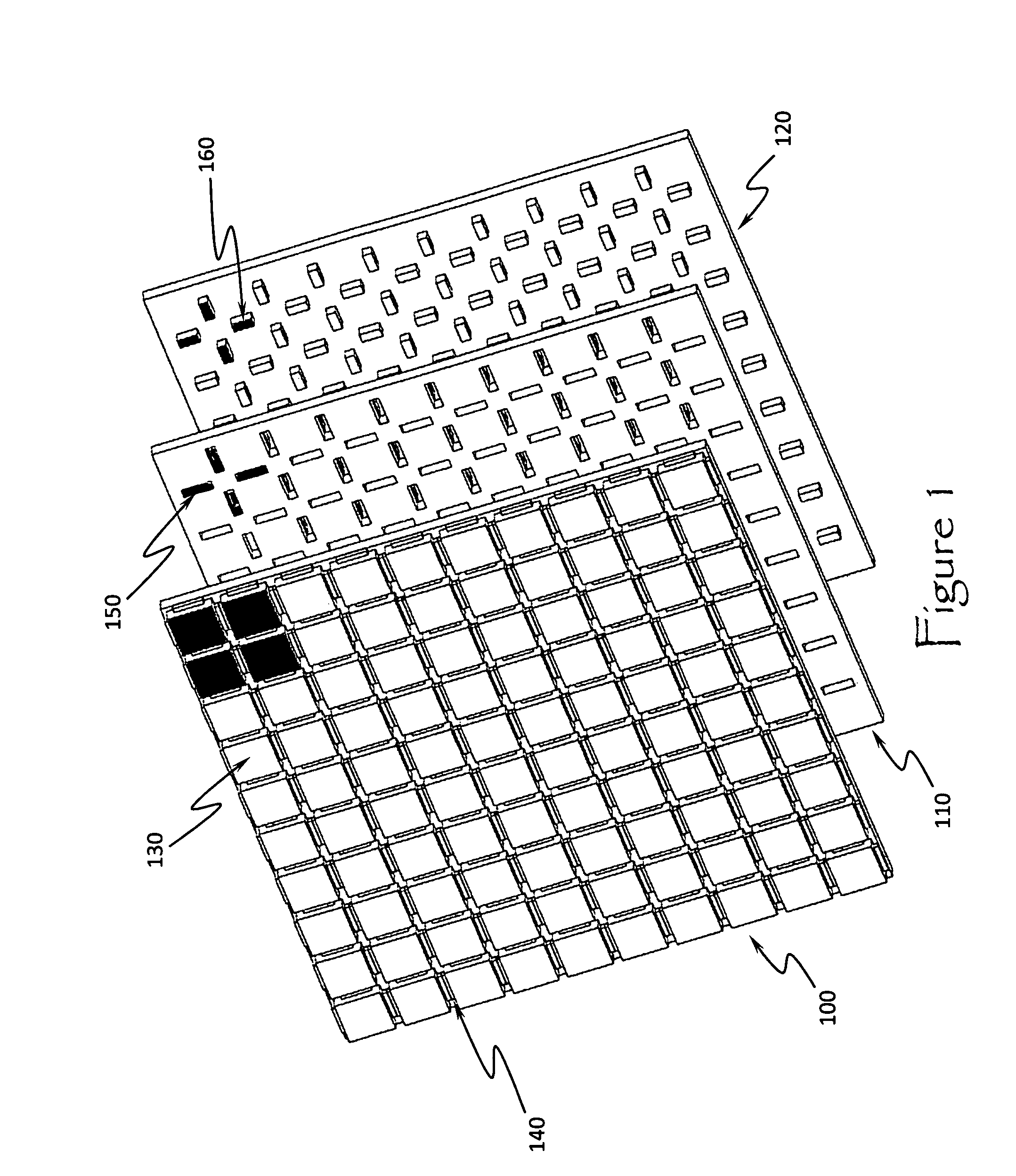
[0035]The present invention describes the design and fabrication of a planar antenna featuring a set of microstrip elements which can be dynamically interconnected and de-interconnected so as to re-pattern the radiating structure of the antenna in order to tune it over a broad frequency band, as well as produce a wide range of beam shapes and pointing directions.

[0036]Referring to FIG. 1, the antenna surface 100 is uniformly covered with a dense array of individual very closely spaced electrically conductive segments or “pixels”130 (preferably a thin metal layer and square in shape) each joined to each of its adjacent segments by a comparatively narrow (square or rectangular) photoconductive connector 140 which is in electrical contact with (or actually overlaps) any two adjacent metallic segments 130, thus filling in the narrow gap between them. Each photoconductive connector 140 is comprised of a photoconductive material made up of CdS, or some variation thereof or substitution th...


PUM


Abstract

A dynamically-reconfigurable feed network antenna having a microstrip patchwork radiating surface wherein individual radiating patches and elements of a stripline feed structure can be connected to and disconnected from each other via photoconductive interconnections. Commands from software alternately turn light from light emitting sources on or off, the light or lack thereof being channeled from an underside layer of the antenna so as to enable or disable the photoconductive interconnections. The resultant connection or disconnection of the radiating patches to each other and to the stripline feed structure will vary the antenna's frequency, bandwidth, and beam pointing.

Description

CROSS-REFERENCE TO RELATED APPLICATIONS[0001]The present application is a continuation-in-part application of and claims priority from related, co-pending, and commonly assigned U.S. patent application Ser. No. 13 / 385,469 filed on Jan. 24, 2012, entitled “Dynamically Reconfigurable Microstrip Antenna System” also by David J. Legare. Accordingly, U.S. patent application Ser. No. 13 / 385,469 is herein incorporated by reference.STATEMENT OF GOVERNMENT INTEREST[0002]The invention described herein may be manufactured and used by or for the Government of the United States of America for governmental purposes without the payment of any royalty thereon.BACKGROUND OF THE INVENTION[0003]1. Technical Field of the Invention[0004]This invention relates generally to the field of communications antennas. More specifically the present invention relates to reconfigurable feed networks for electronically beam-steered planar antenna structures.[0005]2. Background[0006]The development of antennas for us...

Claims


Application Information

Patent Timeline
Patent Type & Authority Patents(United States)
IPC IPC(8): H01Q21/10H01Q1/50
CPCH01Q21/061H01Q21/0006
Inventor LEGARE, DAVID J.
Owner THE UNITED STATES OF AMERICA AS REPRESETNED BY THE SEC OF THE AIR FORCE
Why Eureka
Try Eureka