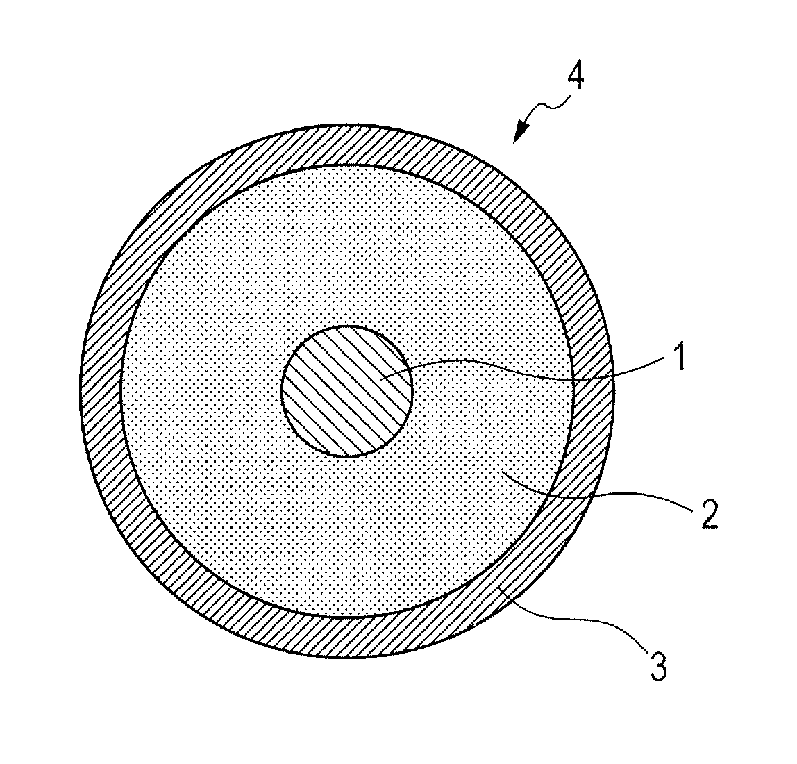
Developing member

a technology of developing member and developing member, which is applied in the direction of electrographic process apparatus, instruments, optics, etc., can solve the problems of interfacial peeling degraded adhesiveness between the elastic layer and the resin layer, etc., and achieve the effect of suppressing fogging

Active Publication Date: 2014-02-18
CANON KK
View PDF11 Cites 21 Cited by
  • Summary
  • Abstract
  • Description
  • Claims
  • Application Information

AI Technical Summary

Benefits of technology

[0011]Further, the present invention is directed to providing an electrophotographic apparatus capable of stably providing a high-quality electrophotographic image.
[0020]According to the present invention, there is provided the developing roller in which the silicone rubber elastic layer and the polyurethane resin layer are firmly adhered to each other and the electrical resistance are appropriately controlled, thereby suppressing fogging.

Problems solved by technology

In the developing member having a configuration in which the elastic layer and the resin layer are laminated as described above, there is a risk in that adhesiveness between the elastic layer and the resin layer may be degraded due to a long-term use, and may cause interfacial peeling between the elastic layer and the resin layer.

Method used


Image

  • Developing member
  • Developing member
  • Developing member

Examples


example 1

[0167](Formation of Elastic Layer)

[0168]A mandrel was obtained by applying a primer (trade name: DY35-051, manufactured by Dow Corning Toray Co., Ltd.) onto a cored bar with a diameter of 6 mm made of stainless steel SUS304 and baking the resultant at a temperature of 150° C. for 30 minutes. Then, the mandrel was placed concentrically with respect to a cylindrical mold with an inner diameter of 11.5 mm, and an addition reaction type silicone rubber composition obtained by mixing the components (a) to (e) described in Table 2 was injected into a cavity created in the mold.

[0169]

TABLE 2(a) Vinyl-terminated polydimethylsiloxane DMS-V42100 parts(trade name, manufactured by GELEST, INC.)by mass(b) Methylhydrosiloxane HMS-3015 parts by(trade name, manufactured by GELEST, INC.)mass(c-1) Carbon Black, Denka Black Powdery Product2 parts by(trade name, manufactured by DENKI KAGAKU KOGYOmassCO., LTD.)(c-2) Carbon Black SUNBLACK2356 parts by(trade name, manufactured by ASAHI CARBON CO.,massLTD....

examples 2 to 25

[0189]The same method as that of Example 1 was performed except that the organopolysiloxane (d-1) was changed to the organopolysiloxanes shown in Table 5 below, and various evaluations were performed. Table 5 shows the results.

examples 26 to 33

[0190]The same method as that of Example 1 was performed except that the organopolysiloxane (d-1) was changed to the organopolysiloxanes shown in Table 5 below and the resin layer coating material (1) was changed to the following resin layer coating material (2), and various evaluations were performed. Table 5 shows the results.

[0191](Production of Resin Layer Coating Material (2))

[0192]The same method as that of the resin layer coating material 1 was performed except that the block polyisocyanate was mixed with the polyol so that the NCO / OH group ratio became 1.1 in the production of the resin layer coating material (1). Thus, a resin layer coating material (2) was obtained.


PUM


Abstract

Provided is a developing roller including elastic layer and resin layer adhered to each other and having an appropriately resistance, thereby suppressing fogging. The developing member comprises a mandrel; an elastic layer; and a resin layer, wherein: the resin layer comprises polyurethane resin obtained by isocyanate and polyol; and the elastic layer includes cured silicone rubber composition comprising (a)-(d):(a) organopolysiloxane having two or more alkenyl groups bonded to silicon atom and having methyl group as a group other than the alkenyl bonded to the silicon;(b) organopolysiloxane having three or more hydrogen atoms bonded to silicon atom and having methyl group as a group bonded to the silicon;(c) carbon black;(d) organopolysiloxane represented by formula (1) and having Mw of 18,000-110,000 and Mw / Mn of 1.0-2.0 (R1 represents alkenyl group, R2 represents functional group reacting with isocyanate, and n represents an integer of 1 or more).

Description

CROSS-REFERENCE TO RELATED APPLICATIONS[0001]This application is a continuation of International Application No. PCT / JP2012 / 007388, filed Nov. 16, 2012, which claims the benefit of Japanese Patent Applications No. 2011-270638, filed Dec. 9, 2011 and No. 2012-249648 filed Nov. 13, 2012.BACKGROUND OF THE INVENTION[0002]1. Field of the Invention[0003]The present invention relates to a developing member and an electrophotographic apparatus.[0004]2. Description of the Related Art[0005]As a developing system in an electrophotographic apparatus such as a copier, a printer, or a receiving device of a facsimile, there has been widely used a one-component developing system using one-component toner.[0006]As a developing member to be used in the developing system using one-component toner, there has been known a configuration in which an electro-conductive elastic layer containing silicone rubber in which carbon black is dispersed is formed on an outer side of an electro-conductive mandrel and...

Claims


Application Information

Patent Timeline
Patent Type & Authority Patents(United States)
IPC IPC(8): G03G15/08
CPCG03G15/0818G03G15/08
Inventor UNO, MASASHIKUSABA, TAKASHIURUSHIHARA, SHOHEISUGIYAMA, RYO
Owner CANON KK
Why Eureka
Try Eureka