Method and system for determining the attitude of an aircraft by multi-axis accelerometric measurements

a multi-axis accelerometric and aircraft technology, applied in the direction of process and machine control, instruments, navigation instruments, etc., can solve the problems of aircraft damage, stalling and falling, aircraft not flying safely,

Active Publication Date: 2014-02-18
THALES SA
View PDF10 Cites 3 Cited by
  • Summary
  • Abstract
  • Description
  • Claims
  • Application Information

AI Technical Summary

Benefits of technology

[0016]An advantage of the invention resides in the replacement of all or part of the gyrometers of a conventional inertial facility by accelerometers with a view to producing a backup navigation system.
[0017]The subject of the invention is thus a method of determination, by an inertial system, of a measurement of the attitude of an aircraft characterized in that it consists at least in determining the angle of pitch θ and / or the angle of heading ψ and / or the angle of roll φ of the said aircraft, each of the said angles of attitude being determined by successive double integration of their second derivative, the said second derivative being determined as the difference between the acceleration measurements delivered by two matched accelerometers, divided by the sum of the respective distances between the said accelerometers and the centre of gravity G of the said inertial system, the pair of accelerometers used for the determination of the angle of pitch θ being disposed on either side of the centre of gravity G along an axis x substantially merged with the longitudinal axis of the aircraft, the pair of accelerometers used for the determination of the angle of heading ψ being disposed on either side of the centre of gravity G along an axis y substantially merged with the transverse axis of the aircraft, the pair of accelerometers used for the determination of the angle of roll φ being disposed on either side of the centre of gravity G along a vertical axis z perpendicular to the plane formed by the x and y axes.
[0018]In a variant embodiment, the method according to the invention furthermore consists in compensating for the errors of calibration of the said accelerometers by correcting the second derivative of the angle(s) of attitude θ, ψ, φ, by a differential bias Δx<sub2>21 < / sub2>divided by the sum of the respective distances between the accelerometers and the centre of gravity G of the said inertial system, the said differential bias Δx<sub2>21 < / sub2>being determined on the basis of the integration, over a given duration T, of the difference between on the one hand, the difference between the acceleration measurements delivered by the pair of matched accelerometers and on the other hand, an unbiased estimate of the second derivative of the angle of attitude θ, ψ, φ that multiplies the sum of the said distances.
[0019]In a variant embodiment of the invention, the measurement of the attitude of the aircraft is used as an item of backup information in support of a reference navigation system.
[0020]In a variant embodiment of the invention, the said reference navigation system delivers the unbiased estimate of the second derivative of the angle or angles of attitude.
[0021]In a variant embodiment, the method according to the invention furthermore consists in correcting the long-term drifts impacting the said attitude measurements by determining at least one compensation δθ of the angle of pitch and / or one compensation δφ of the angle of roll, the said compensations δθ,δφ being determined on the basis of the comparison of the vector {right arrow over (B)}, orthogonal to the plane of the trim as defined by the angles of pitch θ and of roll φ and of the acceleration vector {right arrow over (g)} of the aircraft subject to terrestrial gravity, the said vector {right arrow over (g)} being determined as the gravimetric acceleration of the aircraft at its centre of gravity G, on the basis of the average of the acceleration measurements delivered by two matched accelerometers, the respective distances between two accelerometers of one and the same pair and the centre of gravity G of the said inertial system being fixed to be mutually equal.

Problems solved by technology

In the absence of these parameters, the aeroplane cannot fly safely.
Indeed, if this speed is too high, the aircraft may be damaged; if it is too low, it may stall and fall.
Thus, the measurements carried out by the backup pathway are not independent of those delivered by the operational pathway since they are exposed to common failure modes.
This solution exhibits the drawback of requiring at least two antennas and of increasing the bulk on the aircraft.
Moreover it gives rise to difficulties of synchronization of the two antennas to which are also added problems regarding ambiguity in the phase measured on the basis of the two remote antennas.
A general limitation to the use of satellite radio-navigation signals for the aerial navigation resides in the vulnerability of satellite radio-navigation receivers in relation to the diverse disturbances related to the propagation environment, such as interference, multi-paths or jamming problems.
These disturbances are liable to give rise to significant measurement biases, phase jumps or even dropouts of the phase tracking loops, thus rendering the service momentarily unavailable.
This solution exhibits a drawback in terms of equipment costs, related to the use of several gyrometers.
Indeed the cost of a gyrometer, for example a laser gyrometer, is of the order of several hundred times the order of magnitude of the price of an accelerometer.
Moreover a gyrometer is generally bigger than an accelerometer and consumes more energy than the latter, thereby giving rise, for a conventional inertial facility, to significant overall dimension.

Method used


Image

  • Method and system for determining the attitude of an aircraft by multi-axis accelerometric measurements
  • Method and system for determining the attitude of an aircraft by multi-axis accelerometric measurements
  • Method and system for determining the attitude of an aircraft by multi-axis accelerometric measurements

Examples


Embodiment Construction

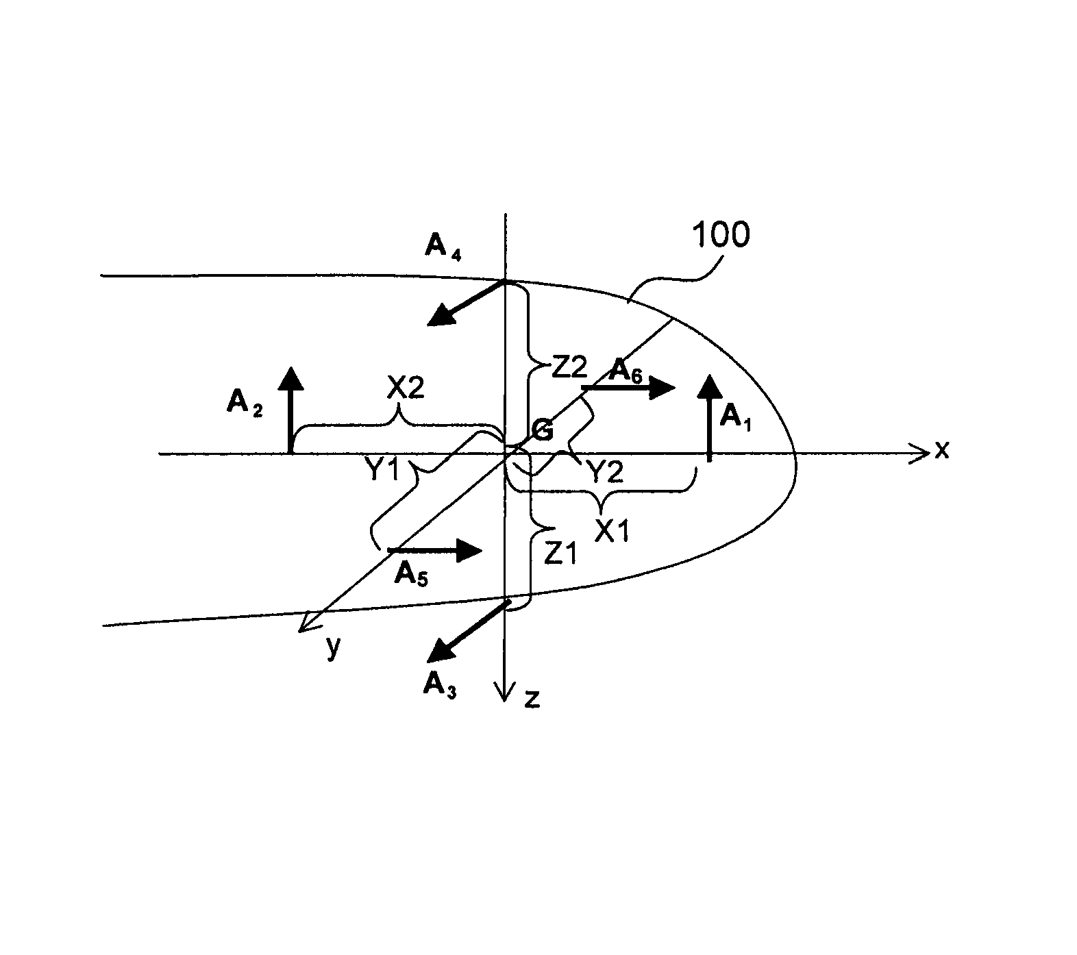
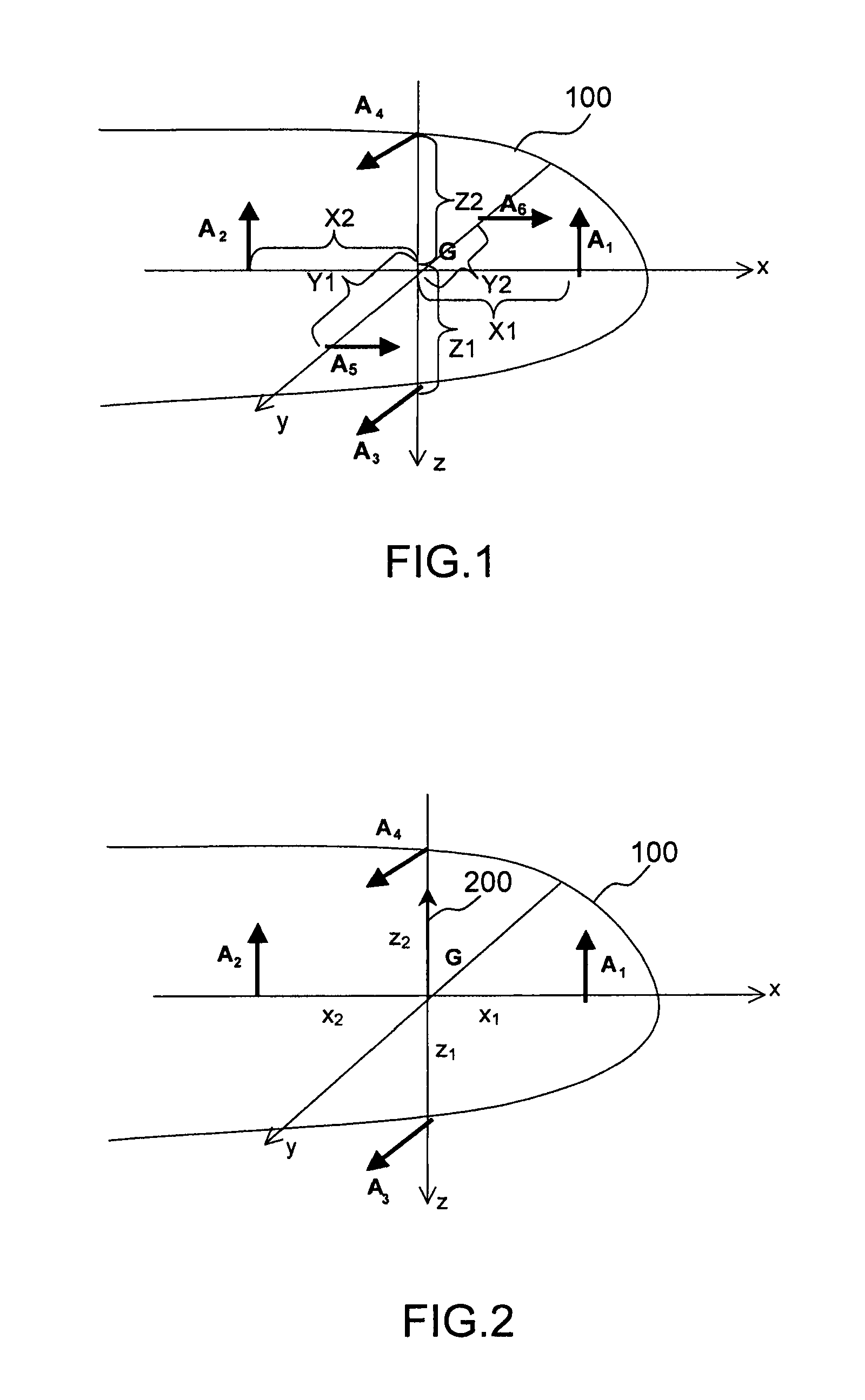
[0032]FIG. 1 shows diagrammatically, in a schematic, the inertial system according to the invention in a first embodiment. The latter is composed of three pairs of mono-axis accelerometers (A1,A2), (A3,A4), (A5,A6) disposed on an aircraft 100 in a fixed reference frame {x,y,z} with respect to this aircraft. In FIG. 1, the six accelerometers are each represented by an arrow oriented in the direction of their respective sensitive axes, that is to say the direction in which the acceleration of the aircraft is measured. The x axis is substantially merged with the longitudinal axis of the aircraft 100, the y axis is substantially merged with the transverse axis of the aircraft 100 and the z axis is a vertical axis perpendicular to the plane formed by the y and z axes.

[0033]The point G represented in FIG. 1 is situated approximately at the centre of gravity of the inertial system according to the invention. The first pair of accelerometers (A1,A2) is disposed on either side of the point G...


PUM


Abstract

An inertial system measures the attitude of an aircraft consisting at least in determining the angle of pitch and / or the angle of heading and / or the angle of roll of the aircraft, each of the said angles of attitude being determined by successive double integration of their second derivative. A pair of accelerometers to determine the angle of pitch being are disposed on either side of the centre of gravity along an axis substantially merged with the longitudinal axis of the aircraft. A pair of accelerometers to determine the angle of heading are disposed on either side of the centre of gravity along an axis substantially merged with the transverse axis of the aircraft. A pair of accelerometers to determine the angle of roll are disposed on either side of the centre of gravity along a vertical axis perpendicular to the plane formed by the other axes.

Description

FIELD OF THE INVENTION[0001]The subject of the present invention is a method and a system for determining the attitude of an aircraft by multi-axis accelerometric measurements. The field of the invention is that of aerial navigation and relates to any type of aircraft, with or without a pilot.[0002]The invention pertains in particular to the field of inertial navigation aid systems.BACKGROUND OF THE INVENTION[0003]The sensors which position an aircraft with respect to the air mass, called anemobaroclinometric sensors, deliver measurements that are fundamental for the aircraft and its safety. Conventionally, these measurements relate to four physical quantities: the total pressure, the static pressure, the temperature (total or static) and the angle of attack. On the basis of primary measurements such as these, elaborate navigation parameters are constructed such as for example, the conventional airspeed of the aircraft, the pressure altitude, the angle of attack or else the Mach num...

Claims


Application Information

Patent Timeline
Patent Type & Authority Patents(United States)
IPC IPC(8): G05D1/00
CPCG01C21/16G01C21/188
Inventor REVOL, MARCMANDLE, JACQUESBIBAUT, ALAINCOATANTIEC, JACQUES
Owner THALES SA
Why Eureka
Try Eureka