
Vacuum cleaning filter bag

a vacuum cleaning and filter bag technology, applied in the field of vacuum cleaning, can solve the problems that the coarse filter would not normally be thought to be suitable, and achieve the effect of improving suction performan

Active Publication Date: 2014-02-25
NUMATIC INTERNATIONAL LIMITED
View PDF38 Cites 1 Cited by
  • Summary
  • Abstract
  • Description
  • Claims
  • Application Information

AI Technical Summary

Benefits of technology

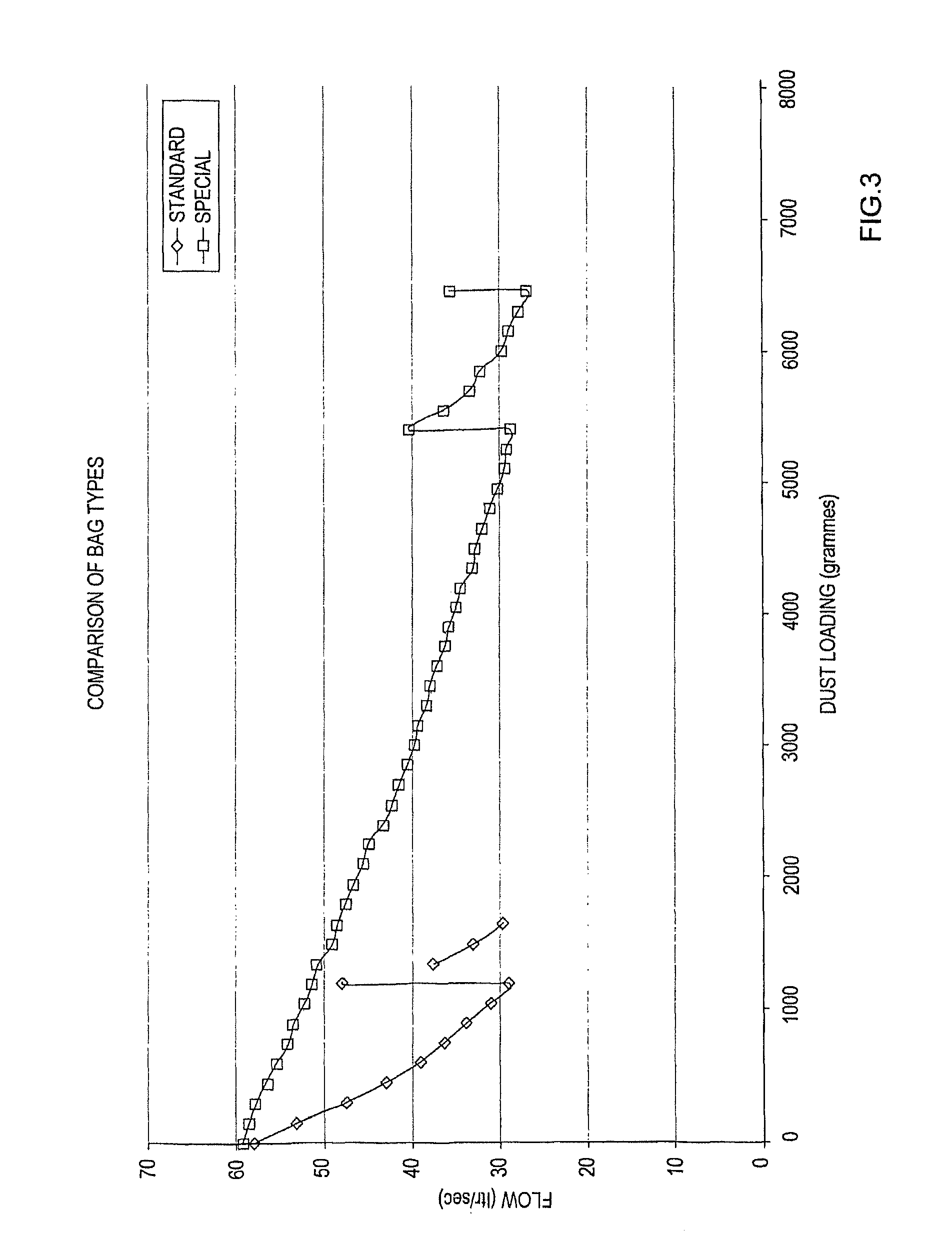
The present invention provides a vacuum cleaner that can collect fine brick and plaster dust without interruption or at least for longer periods of time compared to current products. A filter bag is also provided that improves the suction performance of the vacuum cleaner over time. A coarse filter layer is used upstream of the fine filter to prevent early fouling of the fine filter and allows for a large amount of fine dust to be collected before the suction of the vacuum cleaner degrades. The peripheral edge regions of the coarse filter sheets or web are closed to enhance the collection performance.

Problems solved by technology

This is unexpected because a coarse filter would not usually be thought to be suitable for collecting fine dust which may in theory travel through the filter unhindered.

Method used


Image

  • Vacuum cleaning filter bag
  • Vacuum cleaning filter bag
  • Vacuum cleaning filter bag

Examples


first embodiment

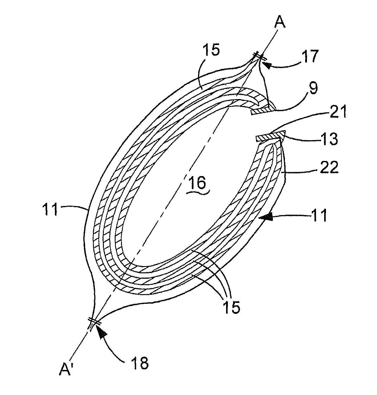
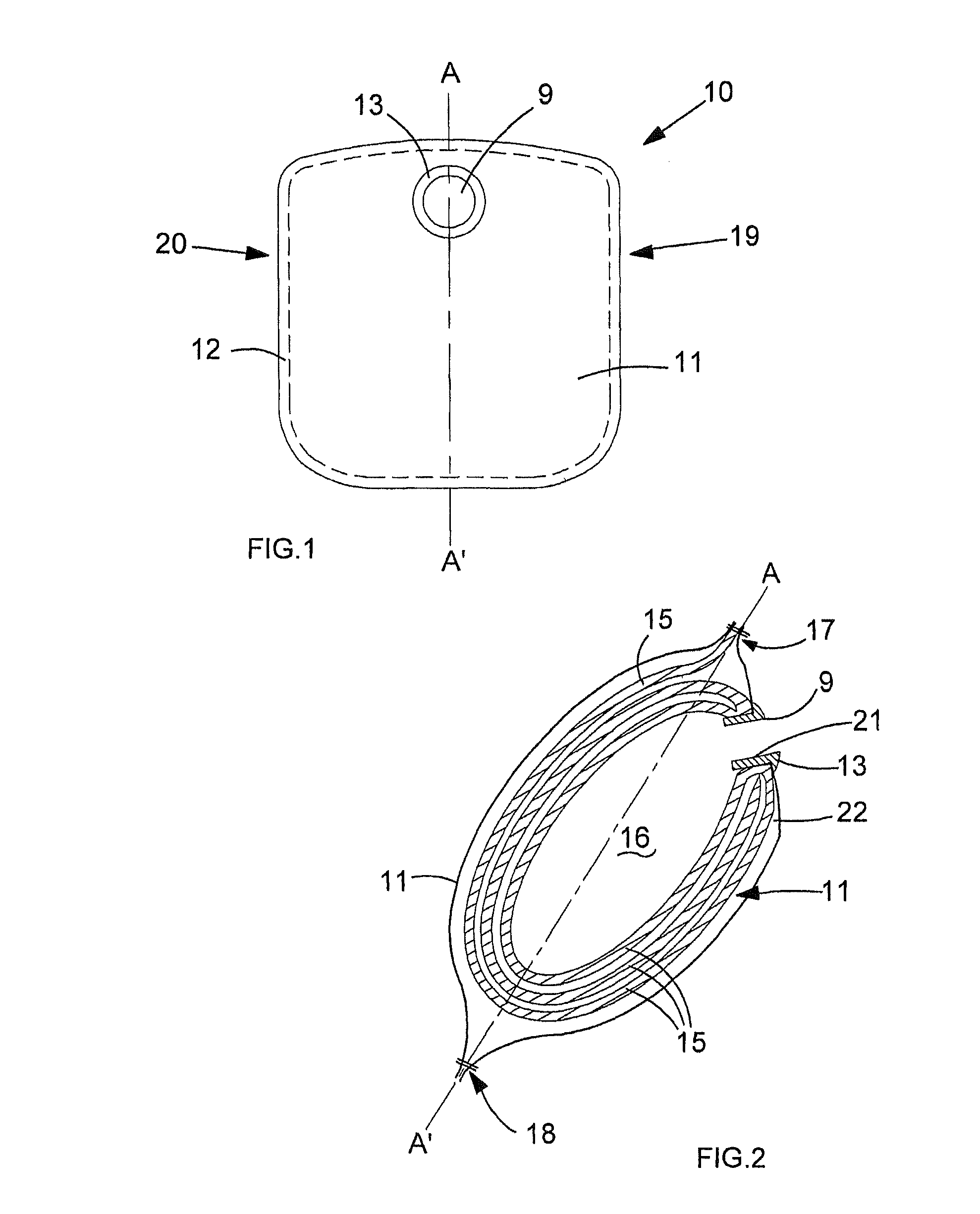
[0033]In FIG. 1 a filter bag for an industrial vacuum cleaner is shown generally as 10. An outer membrane 11 of the bag is formed from two generally square sheets of a fine filter web which are overlapped and heat welded to each other along a peripheral seam 12. The bag has a width of about 60 cm and a height of about 70 cm. An upper central region of the bag is formed with a circular air inlet port 9, which is attached to the membrane via an annular collar portion 13.

[0034]The fine filter web membrane 11 is a multi-layer microporous filter construction intended to retain fine brick and plaster dust. The web is of known composition and structure, essentially comprising three layers laminated to one another. The inner (upstream) layer comprises a spunbonded polymer scrim layer of about 17 g / m2. The middle (sandwich) layer is a melt blown synthetic felt of about 40 g / m2 formed of polypropylene fibre. The outer (clean side) layer is a spun bonded support and fine filtration layer with ...

second embodiment

[0042]A second embodiment of a vacuum cleaner filter bag is shown as 110 in FIGS. 4A, 4B and 4C and in FIG. 5. An outer membrane 111 of the bag is formed from two generally rectangular sheets of a fine filter web which are overlapped and heat welded (by ultrasound) to each other along a continuous peripheral seam 112 (see also FIG. 5). The bag has a width of about 60 cm and a height of about 72 cm. An upper central region of the bag is formed with a circular air inlet port 109, which is attached to the membrane via a rectangular backing plate 113. A rectangular flexible tongue portion 107 projects upwardly from an upper central edge region of the bag. This tongue may be clamped in the vacuum cleaner (not shown) to position the bag securely.

[0043]The fine filter web membrane 111 is a multi-layer microporous filter construction as described in the foregoing in relation to the first embodiment. Such three-layer filter membranes are known in the art and are available from commercial sup...


PUM


Abstract

The disclosure relates to the field of vacuum cleaning and in particular the collection of air-entrained debris, in a filter bag. The filter bag is for use in vacuum cleaning apparatus, and comprises fine planar filtration means in the form of a collection bag and coarse planar filtration means both being adapted to be placed in a suction-induced air stream with the coarse filtration means disposed upstream of the fine filtration means, wherein the fine filtration means serves to provide a fine filter for retaining dust particles and wherein the coarse filtration means comprises a relatively coarse filter material having a thickness of at least 4 mm which provides a matrix volume in which dust may be collected. The volume occupied by the coarse filtration means comprises at least 2%, preferably at least 5%, most preferably at least 10% of the maximum internal volume defined by the collection bag.

Description

BACKGROUND OF THE INVENTION[0001]The present invention relates to the field of vacuum cleaning and in particular the collection of air-entrained debris, for example in a filter bag.[0002]Domestic and upright type vacuum cleaners are typically equipped with porous paper bags into which dirt-laden air lifted from a floor or carpet is drawn by a vacuum drive. Cyclonic separators are also well known in both a domestic and industrial contexts for separation of air-entrained particles from an air stream.[0003]Industrial and commercial bin-type cleaners frequently avoid using a bag for collection, so as to avoid bag replacement. In this case dirt is drawn from a floor surface into a tubular wand and collected directly in a drum or bin rather than a bag. A filter cup or layer may be used to cover a vacuum drive port typically in an upper end region of the bin. The bag prevents fine particles from leaving the bin during use and fouling the vacuum drive (typically an electric motor and impell...

Claims


Application Information

Patent Timeline
Patent Type & Authority Patents(United States)
IPC IPC(8): A47L9/14
CPCB01D39/1623B01D2239/065B01D2275/10A47L9/14B24B55/10
Inventor DUNCAN, CHRISTOPHER, ROBERT
Owner NUMATIC INTERNATIONAL LIMITED
Learn More