System and method for thermal gradient control in thin shell structures

a thin shell and gradient control technology, applied in the direction of drying machines with progressive movements, lighting and heating apparatus, and rolling machines, can solve the problems of high stress conditions at and near the connection of thin strips of the shell large and expensive apparatuses, and high stress conditions at the thin strip connection and the thick end members. , to achieve the effect of reducing the width of the foraminous area

Active Publication Date: 2014-02-25
VALMET OY
View PDF17 Cites 6 Cited by
  • Summary
  • Abstract
  • Description
  • Claims
  • Application Information

AI Technical Summary

Benefits of technology

[0013]In one embodiment, this foraminous wall of the cylindrical shell comprises two spaced-apart tiers of bent strips disposed between the straight strips and an axial channel extends between the two tiers of bent strips from one end member to the other. In this embodiment, at least one impervious thin strip deckle band is disposed about the surface of the annular cylinder and aligned at one fixed edge with an end member, thereby reducing the width of the foraminous area of the thin shelled roll. Additionally, at least one impermeable insert is aligned at and / or near the free edge of impervious thin strip deckle band and extends through a radial channel and across the entire axial channel and at least a portion of the faces of the two tiers of bent strips so as to block the axial channel therebetween and prevent the passage of air therethrough to the end member.

Problems solved by technology

Cylindrical Honeycomb® drying rolls, such as those described by U.S. Pat. Nos. 3,259,961, 3,590,453, and 4,050,131, are well known in the art and typically these rolls are large and expensive apparatuses.
If the sheet width, however, fails to precisely match the width of the exposed shell, either taken alone or left uncovered by the deckle band, hot supply air leaks by the end of the sheet, entering the shell and running along the axial channel between at least the layers of bent strips (i.e. the spaced apart inner diameter and outer diameter corrugation layers).
This temperature difference causes the support structure to exert significant restraining forces on the shell, resulting in high stress conditions at and near the connection of the thin strips of the shell and the thick end members.
This causes a sharp thermal gradient at the intersection of the thin strips and thick end members and these steep thermal gradients cause high stresses.
This adds time and inefficiency to the overall manufacturing process for drying travelling webs.

Method used


Image

  • System and method for thermal gradient control in thin shell structures
  • System and method for thermal gradient control in thin shell structures
  • System and method for thermal gradient control in thin shell structures

Examples


Embodiment Construction

[0029]The present invention solves the thermal stress problems associated with foraminous, rotating thin shelled dryers for drying permeable and semi-permeable woven and nonwoven webs to produce sheet materials.

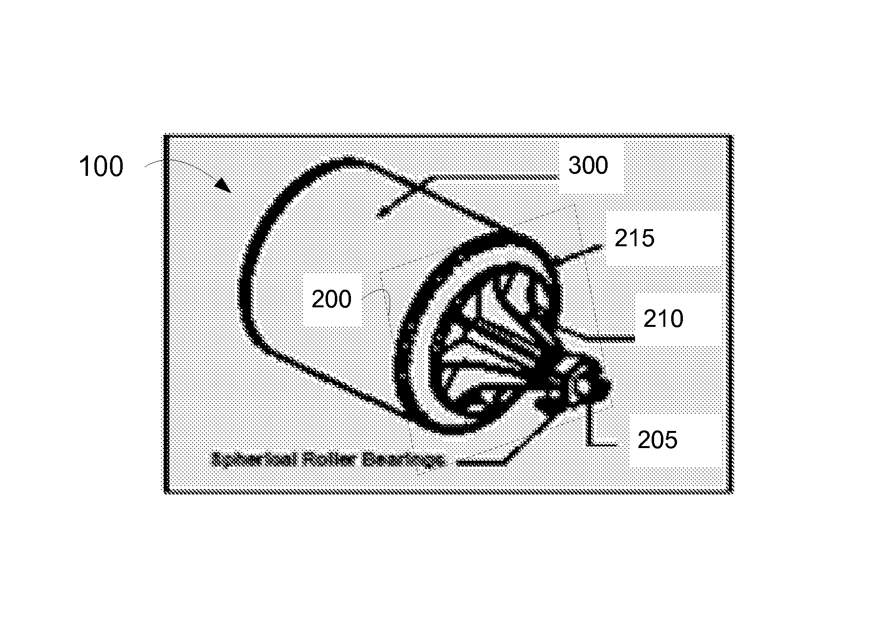
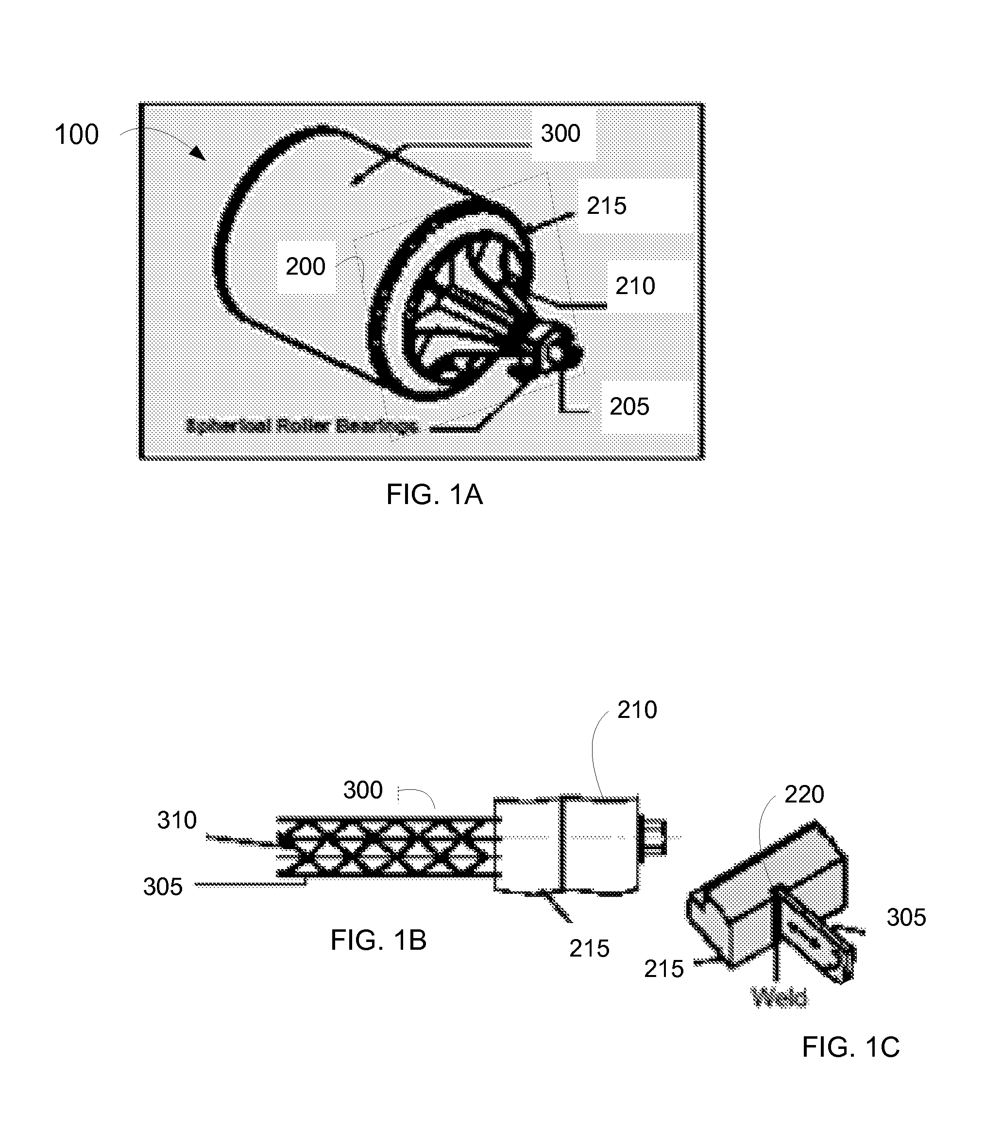
[0030]FIGS. 1A through 4C depict portions of an embodiment of a Thru-Air® brand through air dryer shell. FIG. 1A depicts a typical rotating cylindrical dryer shell system 100 comprising end members 200 supporting a foraminous cylindrical shell 300 on both ends. One embodiment of an end member 200 comprises a journal 205 about which the cylindrical shell 300 rotates, and a head 210 joining an end ring 215 to the journal. The end ring 215 supports the shell 300 and typically is manufactured from a durable metal capable of withstanding a manufacturing environment, such as but not limited to carbon steel or stainless steel. The thicknesses of the end ring 215 and head member 210 are many times far greater than that of the thin strips of material forming the dividers 305 and corru...


PUM

PropertyMeasurementUnit
temperatureaaaaaaaaaa
thickaaaaaaaaaa
thickaaaaaaaaaa

Abstract

Described herein are devices and methods for reducing thermal stresses in a rotating, foraminous thin-shelled roll for drying permeable and semi-permeable webs by blocking axial flow of heated air through an axial channel formed between two corrugated layers in the shell. The axial channels extend between spaced-apart, parallel end members each having an inner face, and a plurality of alternating straight thin divider strips and bent thin strips extending axially between and evenly-spaced around the circumference of the inner faces of the end members to form an annular cylinder with radial channels therethrough. Affixing at least one impermeable insert into a radial channel so that it extends through the radial channel and across at least a portion of the faces of the two tiers of bent strips blocks the axial channel therebetween and prevents the passage of air therethrough to the end member.

Description

BACKGROUND[0001]1. Field of the Invention[0002]The present invention relates to the field of permeable and semi-permeable woven and non-woven web drying, and in particular to reducing thermal stresses in a Honeycomb® shell for drying such webs.[0003]2. Discussion of Background Information[0004]Cylindrical Honeycomb® drying rolls, such as those described by U.S. Pat. Nos. 3,259,961, 3,590,453, and 4,050,131, are well known in the art and typically these rolls are large and expensive apparatuses. The air permeable shells of such rolls comprise alternating thin straight and thin undulated strips that extend between thick metal end members, thereby effectively forming a cylindrical shell comprised of corrugated layers. The undulated strips may form, for example, half-hexagonal or triangular-shaped openings between the straight strips.[0005]During the drying process, heated air impinges on a wet web traveling on the rotating roll. The heated process air travels through the web and betwee...

Claims


Application Information

Patent Timeline
Patent Type & Authority Patents(United States)
IPC IPC(8): F26B11/02
CPCF26B13/16Y10T29/49826D21F5/021
Inventor PARKER, RICHARD, A.
Owner VALMET OY
Why Eureka
Try Eureka