
Ceiling panel for lining interiors of vehicles

a technology for interior linings and ceiling panels, which is applied to aircraft floors, building components, aircraft accessories, etc., can solve the problems of reducing the overall weight of the ceiling panel, reducing the cost of ensuing increased costs, and damage to components of the interior lining of the vehicle, for example cables, insulation, etc., so as to reduce the disadvantage of known devices, reduce the cost of manufacturing, and the effect of assembling and disassembling the ceiling panel as quickly and simply

Active Publication Date: 2014-02-25
FACC
View PDF32 Cites 11 Cited by
  • Summary
  • Abstract
  • Description
  • Claims
  • Application Information

AI Technical Summary

Benefits of technology

The present invention is a new ceiling panel and lining that can be easily assembled and disassembled without tools. The panel includes fixation devices and counter pieces that can be connected together without tools to minimize the offset between panels. The fixation devices and counter pieces are small and inexpensive, and the manufacturing process doesn't require specialized labor. The goal of this invention is to create a ceiling panel and lining that are easy and cost-effective to manufacture, and can be assembled and disassembled quickly. Additionally, the invention allows for a certain amount of movement within the vehicle without causing any damage or losing any components.

Problems solved by technology

The fixation devices and counter pieces can be manufactured to be relatively small and cheaply so that the overall weight of the ceiling panel is only insignificantly increased and the ensuing increased costs can be kept very low.
A disadvantage with bent metal parts are the ensuing sharp edges, which can lead to damage to components of the interior lining of the vehicle, for example, cables, insulation, etc.
In order to obviate this problem, corresponding protective covers can be provided around the bent metal parts, or the bent metal parts can, for example, be provided with a plastic layer, which however again increases the manufacturing expense and the weight.

Method used


Image

  • Ceiling panel for lining interiors of vehicles
  • Ceiling panel for lining interiors of vehicles
  • Ceiling panel for lining interiors of vehicles

Examples


Embodiment Construction

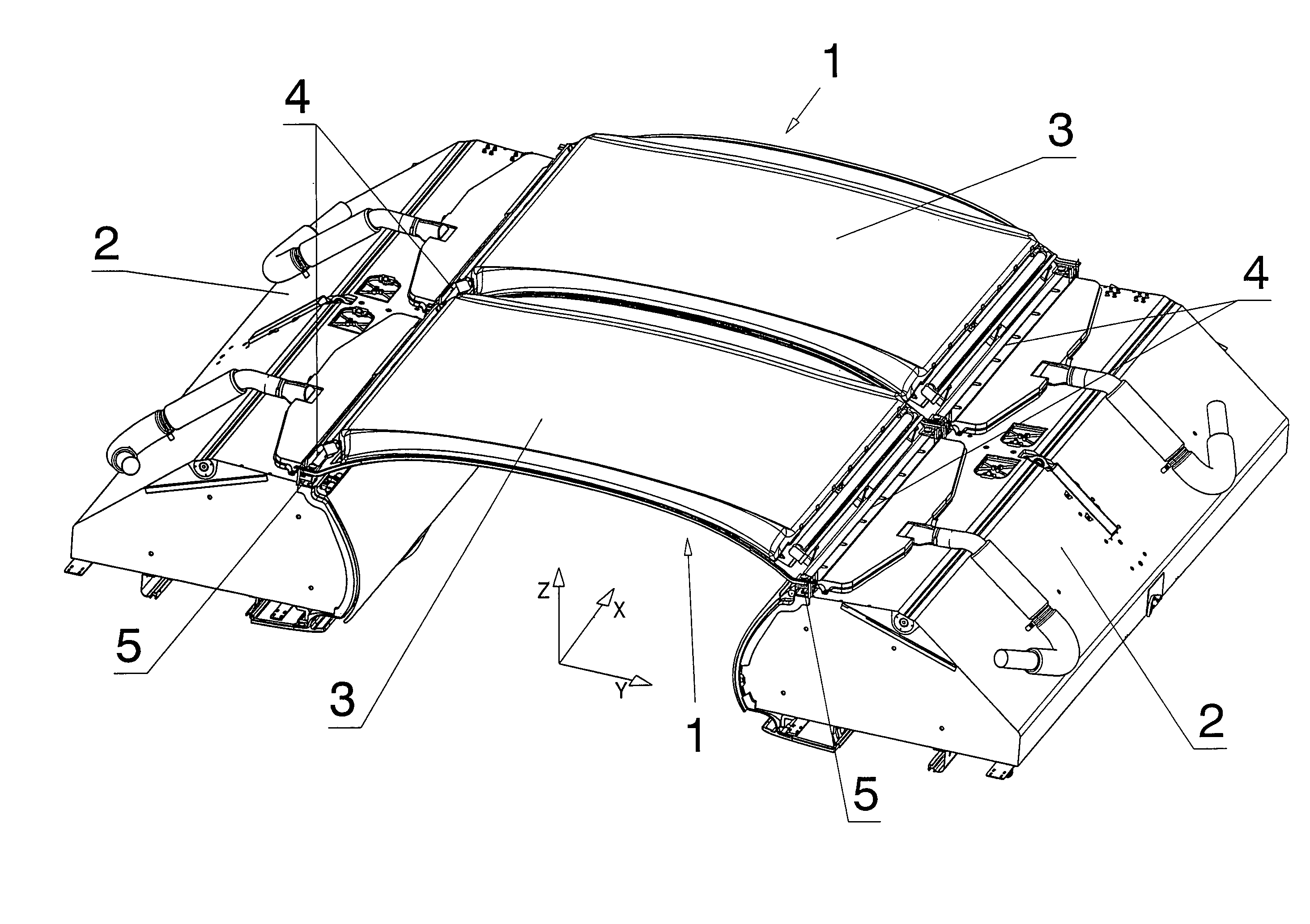
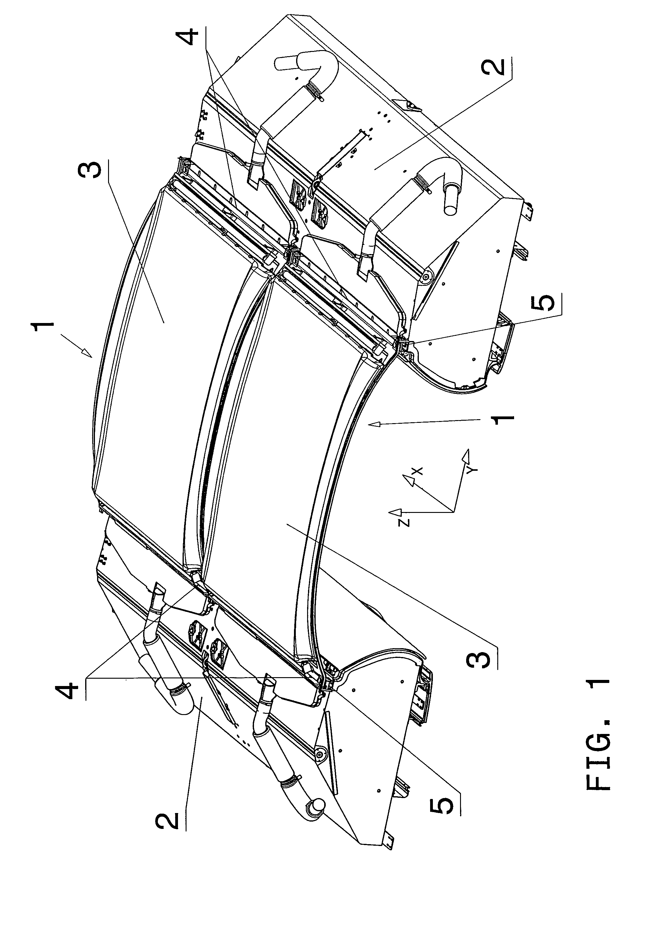
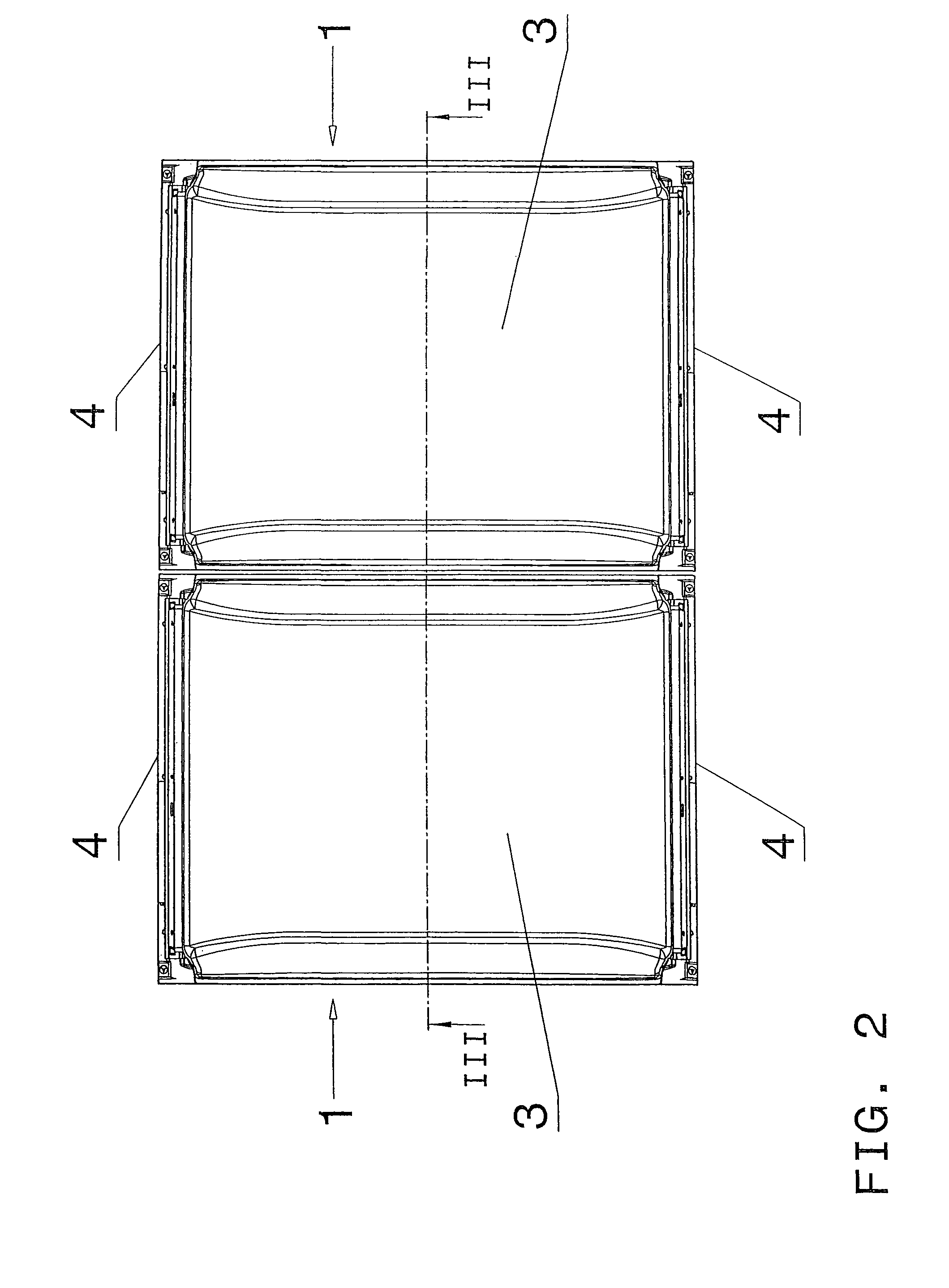
[0038]FIG. 1 shows a perspective view of a part of a ceiling lining in the interior of an aircraft, comprising two ceiling panels 1, which define the interior of the aircraft above the luggage storage compartments 2. The ceiling panels 1 each consist of a plastic composite element 3 having elements 5 disposed on the lateral edges 4 extending substantially in the movement direction X of the aircraft for fastening to a supporting structure of the aircraft or parts associated therewith. Details of the configuration of the fastening elements 5 are not apparent in the figures. The fastening elements 5 are preferably formed by appropriate movable bearings on one lateral edge 4 and by appropriate fixed bearings on the opposite lateral edge 4.

[0039]Since the ceiling panels 1 are broader than the clear width between the luggage storage compartments 2, during installation and dismantling, they must be threaded in obliquely between the luggage storage compartments 2 and suitably fastened above...


PUM


Abstract

A ceiling panel for lining the interior of a vehicle, particularly an airplane, includes a plastic composite element having elements disposed at lateral edges extending substantially in a movement direction of the vehicle for fastening to a supporting structure of the vehicle or parts connected thereto. At least one fixation device is provided on a transverse edge disposed substantially transversely to the movement direction and at least one counter piece is provided on an opposite transverse edge, as viewed in the movement direction, to avoid an offset in a perpendicular direction between consecutive ceiling panels. The at least one fixation device is configured to complement the at least one counter piece and a form-locking connection can be produced and detached again without tools in the substantially perpendicular direction, by the interaction of each fixation device with a respective counter piece.

Description

BACKGROUND OF THE INVENTIONField of the Invention[0001]The invention relates to a ceiling panel for lining the interior of a vehicle, in particular an aircraft, comprising a plastic composite element having elements disposed at the lateral edges extending substantially in the movement direction of the vehicle for fastening to a supporting structure of the vehicle or parts connected thereto.[0002]The present invention further relates to a ceiling lining for the interior of a vehicle, in particular an aircraft, comprising a plurality of ceiling panels disposed successively in the movement direction of the vehicle.[0003]Although the present invention is primarily provided for use in aircraft, an application in other vehicles in which a weight reduction of the component parts is essential such as, for example, speed boats, high-speed trains or the like, is also feasible.[0004]Ceiling panels and other covering panels used to configure the interior of aircraft or the like are increasingly...

Claims


Application Information

Patent Timeline
IPC IPC(8): E04B2/00E04C2/00
CPCB61D17/18Y02T50/46B60R2013/0287B63B29/02B60R13/0206B64C1/066B60R2013/0293B60R2013/0281B60R13/0225B60R13/0275B60R13/02Y02T50/40
Inventor KERNMAYER, GEORGSTANDHARTINGER, MANFRED
Owner FACC
Learn More