Door machine having chain disk locking mechanism

a technology of locking mechanism and chain disk, which is applied in the direction of wing accessories, braking systems, door/window protective devices, etc., can solve the problems of shortening the life of the rolling door, high chance of failure, and complex structure of the clutch mechanism, so as to reduce the cost, simplify the mechanical components, and extend the service life

Active Publication Date: 2014-02-25
HSIEH CHUNG HSIEN
View PDF4 Cites 16 Cited by
  • Summary
  • Abstract
  • Description
  • Claims
  • Application Information

AI Technical Summary

Benefits of technology

[0007]The main object of the present invention is to provide an electric door machine having a chain disk locking mechanism which not only dispenses with clutch mechanism used in conventional door machine so as to reduce cost, but also has simplified mechanical components and its assembly and convenience in maintenance so as to extend life span of service. Further, when the chain disk of the present invention is operated, for example by pulling manually, the rolling door is rolled upward / downward; when cease pulling the chain, braking is immediately effected so as to lock the rolling door from moving upward / downward. Thus, switching operation by a conventional clutch is not required.
[0008]Another object of the present invention is to provide an electric door machine having a chain disk locking mechanism which can increase / decrease the number of the brake disk and the brake wheel arranged with great flexibility according to the practical demand, such as the horsepower of the electric motor, the weight of the rolling door, or some other factors, so as to adjust the brake force.
[0011]Preferably, each axial slot includes two end walls disposed respectively on both sides of the axial slot and are adjacent to the two second end faces. Each end wall is provided with a compression spring which force the moving pins to disengage from the end walls. In this manner, the compression springs can push the multiple moving pins to contact the first end face so that the moving pins are engaged in the first radial gap to lock the stationary shaft. The present invention may further comprise a reduction mechanism coupling to the drive shaft of the electric motor for reducing the output speed of the electric motor. The reduction mechanism is intended to cooperate with the rolling door to control the rolling upward / downward speed of the rolling door. Hence, the reduction mechanism may be installed when necessary, and the degree of reduction provided by the reduction mechanism can be adjusted according to practical demand.
[0012]Furthermore, this invention comprises an electromagnetic brake module which includes a brake disk, an electromagnetic force generator, and an elastic element, one end of the drive shaft being connected with an end disk, wherein the brake disk and the elastic element are fitted on the stationary shaft, and the brake disk is located at one side surface of the end disk, and the elastic element forces the brake disk to press against the end disk so as to effect braking. When the electric motor is activated, the electromagnetic force generator is energized to disengage the brake disk from the end disk to release the drive shaft. Therefore, when the electric motor is in non-operation state, the drive shaft of the electric motor is locked by the chain disk locking mechanism so that the drive shaft cannot be rotated freely. Besides, the stationary shaft may also be braked by the electromagnetic brake module so that the drive shaft of the electric motor cannot be rotated freely. Hence, double braking effect can be achieved.
[0013]Further, the end disk is connected to a brake wheel in axial direction, while the brake disk is located between the end disk and the brake wheel. Further, the electromagnetic force generator may comprise a shaft disk which is fitted on the stationary shaft and is located between the electromagnetic force generator and brake wheel. Furthermore, the elastic element can force the shaft disk and the brake disk to press against the brake wheel and the end disk to effect braking. When the electric motor is activated, the electromagnetic force generator is energized to attract the shaft disk so that the shaft disk linking the brake disk is disengaged from the end disk and the brake wheel to release the drive shaft. In this manner, the present invention can provide additional brake wheel to increase the brake force. In other words, this invention can increase or decrease the quantities of the brake disk and the brake wheel arranged with great flexibility according to the practical demand such as the horsepower of the electric motor, the weight of the rolling door, or some other factors, so as to adjust the brake force.

Problems solved by technology

Frequent opening / shutting may cause shorter lifetime of the rolling door.
However, the clutch mechanism is complicated in structure and very expensive, what is more, the chances of failure are high.

Method used


Image

  • Door machine having chain disk locking mechanism
  • Door machine having chain disk locking mechanism
  • Door machine having chain disk locking mechanism

Examples


Embodiment Construction

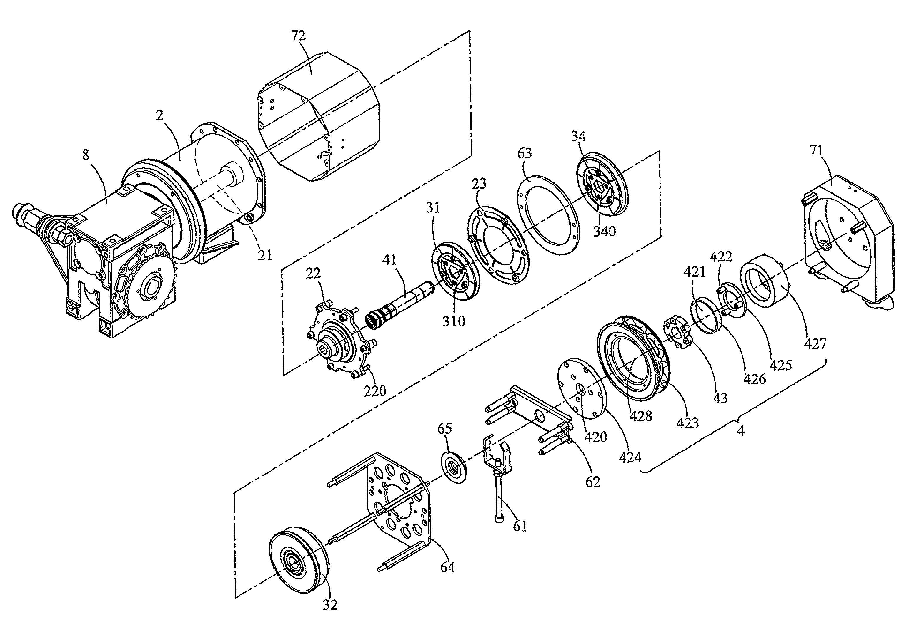
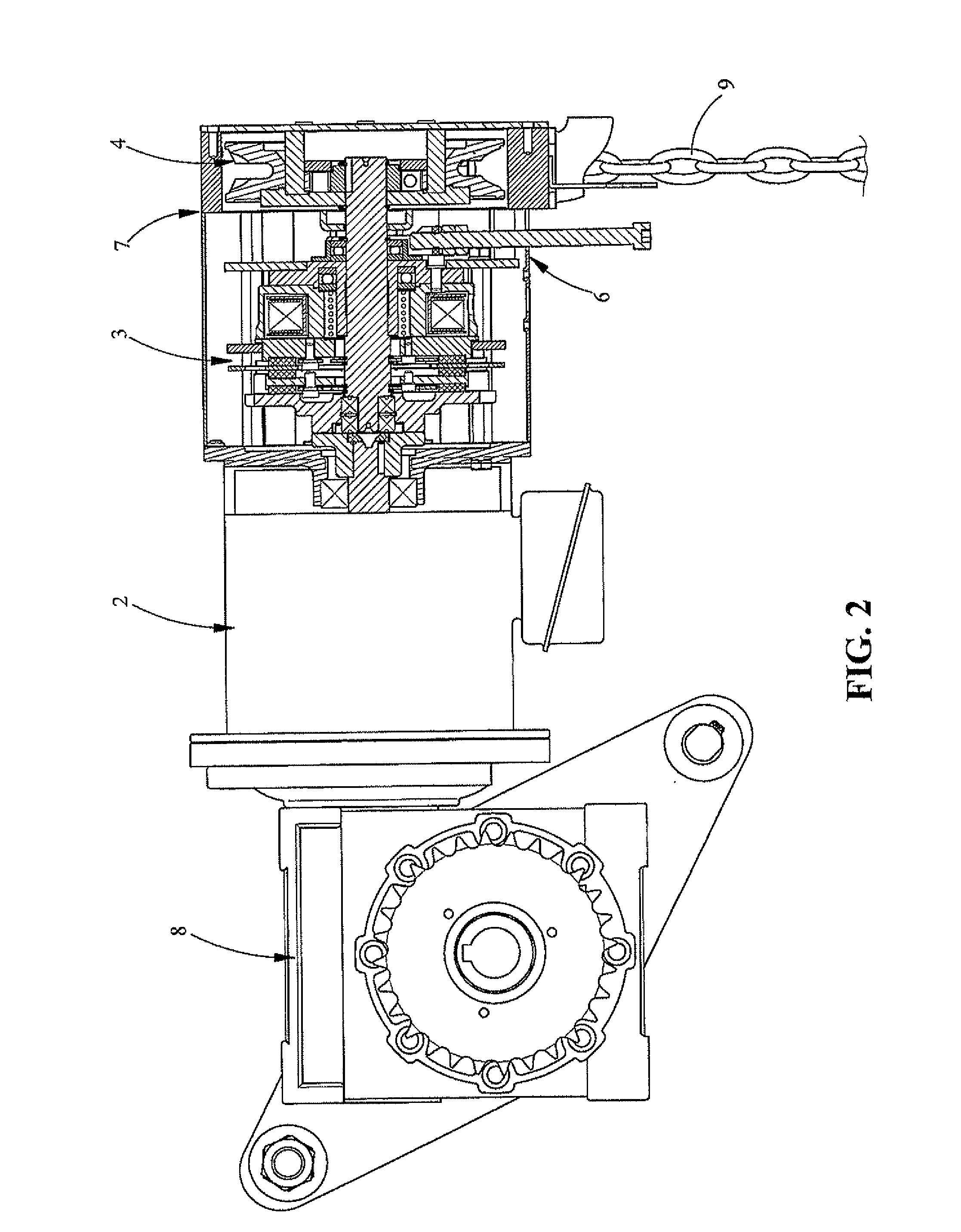
[0027]FIG. 2 is a schematic view showing a preferred embodiment of the electric door machine of the present invention. As shown in FIG. 2, the electric door machine comprises an electric motor 2, an electromagnetic brake module 3, a chain disk locking mechanism 4, a brake release mechanism 6, an outer casing 7, and a reduction mechanism 8. The electromagnetic brake module 3, the chain disk locking mechanism 4, and the brake release mechanism 6 are accommodated in the outer casing 7. The outer casing 7 enclosing the aforementioned mechanisms is connected at one side of the electric motor 2, and the reduction mechanism 8 connected at the other side. The reduction mechanism 8 may reduce the output speed of the electric motor 2 for moving the rolling door (not shown). In other words, the reduction mechanism 8 is designed to control the upward / downward rolling speed of the rolling door. The degree of reduction provided by the reduction mechanism 8 can be adjusted according to practical d...


PUM


Abstract

A door machine having an electric motor and a chain disk locking mechanism. The chain disk locking mechanism includes a chain disk, an engaging rotary block, a stationary shaft and a plurality of moving pins. When the chain disk is pulled to rotate, the fixed pins of the chain disk press the moving pins so as to push the engaging rotary block to rotate with the stationary shaft together. When the stationary shaft is pulled to rotate, the engaging rotary block prohibits the moving pins from rotation. When the chain disk is pulled manually, the rolling door can be rolled upward or downward; when cease pulling the chain disk, braking is immediately effected so as to prevent the rolling door from moving upward or downward. Hence, the clutch mechanism can be omitted for cost saving and the structure of the mechanism can be simplified.

Description

BACKGROUND OF THE INVENTION[0001]1. Field of the Invention[0002]This invention relates to a door machine having a chain disk locking mechanism, more particularly to an electric rolling door having a feature of opening / shutting in high speed, which is suitable for warehouse or garage needing frequent opening / shutting.[0003]2. Description of the Related Art[0004]Accompanying with the rising of Environment Protection and energy saving consciousness, for example, of avoiding cold air or warm air from leaking to outside, the opening / shutting of electric rolling door used for ordinary warehouse or garage becomes very frequent. Frequent opening / shutting may cause shorter lifetime of the rolling door. Further, in order to prevent cold / warm air from leaking to outside, there is a demand to increase the running speed of the electric rolling door.[0005]Conventional electric door machine has a clutch which switches between the motor driven rolling and manual chain disk rolling. However, the clu...

Claims


Application Information

Patent Timeline
Patent Type & Authority Patents(United States)
IPC IPC(8): E06B9/74F16D55/22E06B9/56
CPCE05Y2800/11E06B2009/807E05F15/1653E05Y2900/146E06B9/80E05F15/10E05F15/684E05Y2900/00E05Y2900/106
Inventor HSIEH, CHUNG, HSIEN
Owner HSIEH CHUNG HSIEN
Why Eureka
Try Eureka