
Device for dispensing plastic fasteners

a technology for fasteners and devices, applied in the field of plastic fasteners, can solve the problems of significant drawbacks, time-consuming repair, and significant increase in the likelihood of jamming of the fastener, and achieve the effect of reducing the likelihood of jamming

Active Publication Date: 2014-02-25
AVERY DENNISON CORP
View PDF50 Cites 9 Cited by
  • Summary
  • Abstract
  • Description
  • Claims
  • Application Information

AI Technical Summary

Benefits of technology

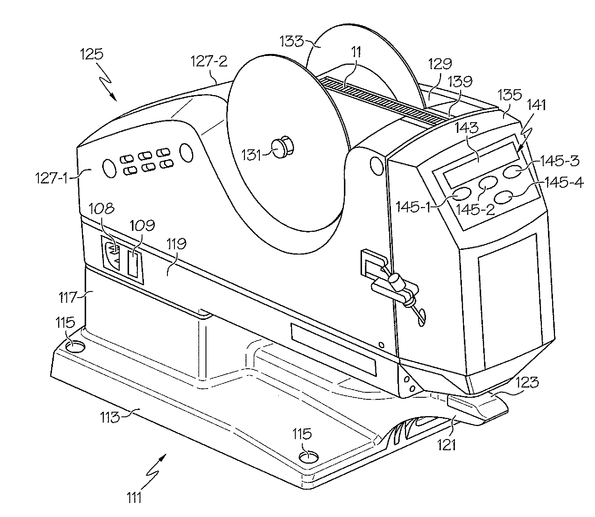
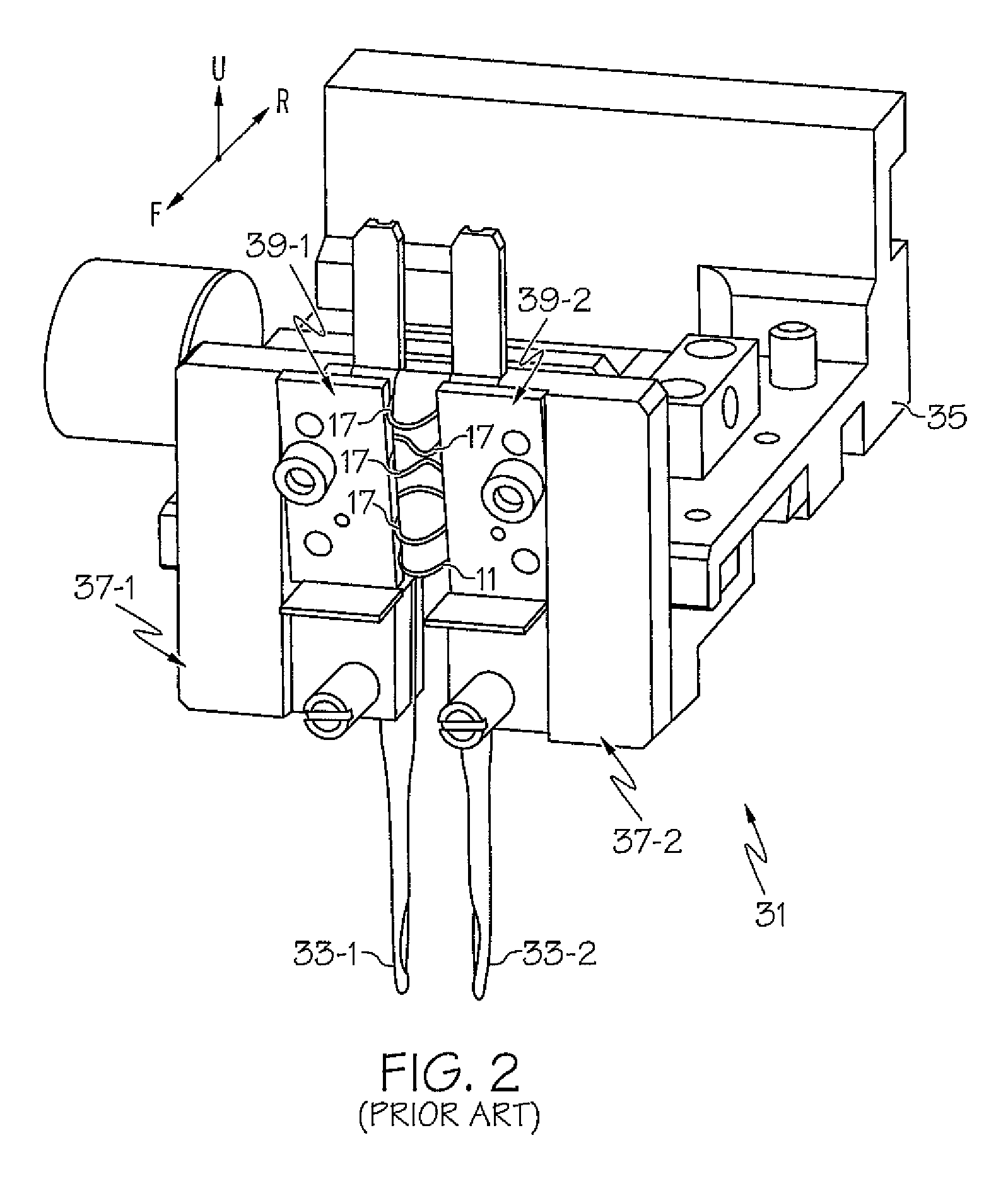
The present invention provides a device for dispensing plastic fasteners from a supply of fastener stock. The device includes a head assembly and a motor for driving the head assembly through its actuation cycle. The head assembly is designed to limit distortion of the cross-links for the supply of fastener stock within a single plane. The device is also designed to adjust the spacing between the pair of hollow needles and reliably feed the ladder stock into proper alignment behind the pair of hollow needles to minimize the likelihood of fastener jamming. Overall, the device enables efficient and reliable dispensing of plastic fasteners.

Problems solved by technology

In this capacity, the dispensed fastener serves to secure the article to the display card in an inconspicuous and unobtrusive manner.
Although well known and widely used in commerce, fastener dispensing devices with variable needle spacing capabilities have been found to suffer from a notable drawback.
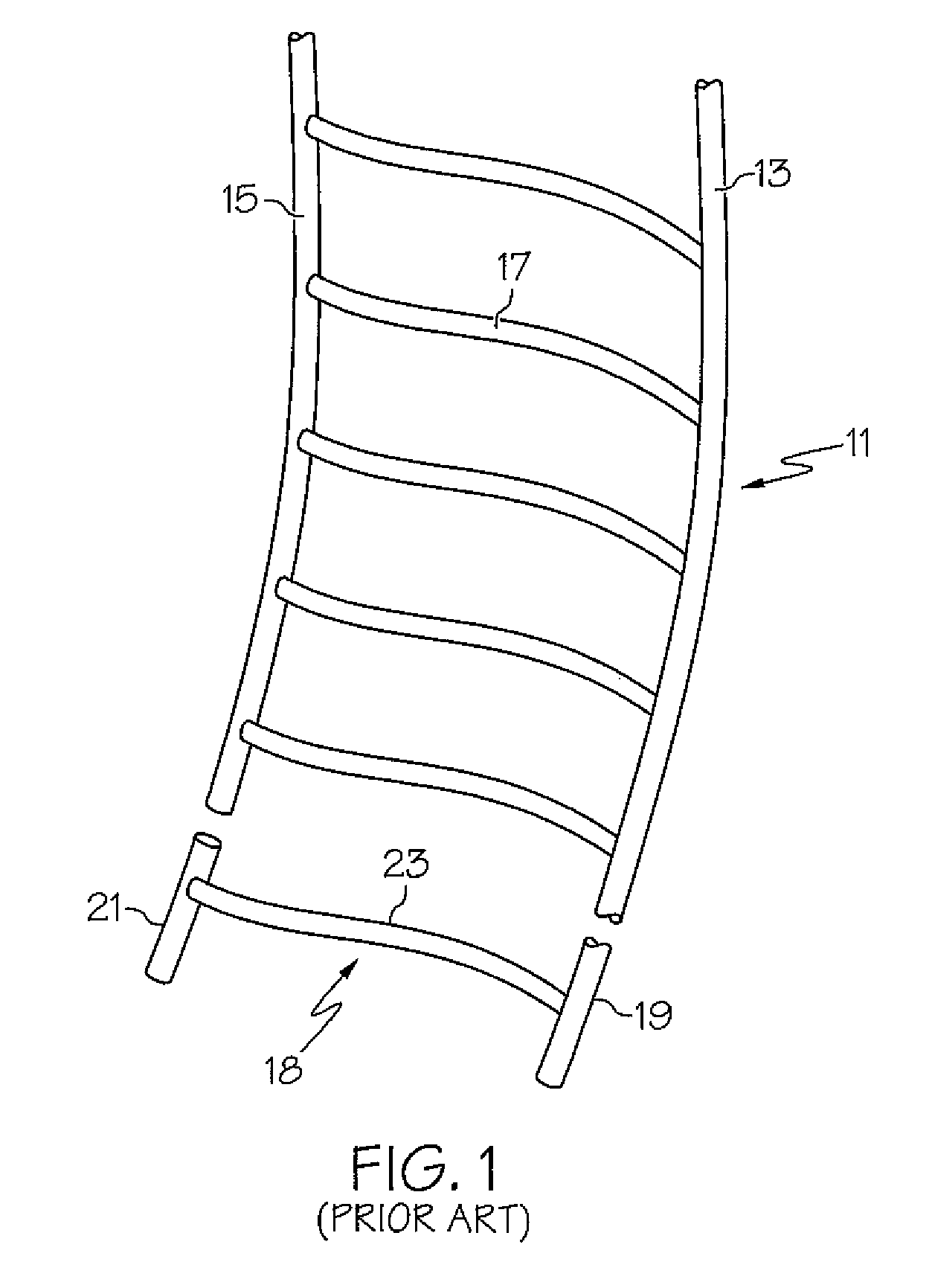
When a fastener dispensing device with closely spaced needles is used in high speed dispensing applications, the presence of irregularly patterned filament distortions in the ladder stock has been found to significantly increase the likelihood of jamming.
Once a jamming condition occurs, the fastener dispensing device needs to be shut down until a relatively labor-intensive and time-consuming repair can occur to remove the jammed ladder stock, which is highly undesirable.

Method used


Image

  • Device for dispensing plastic fasteners
  • Device for dispensing plastic fasteners
  • Device for dispensing plastic fasteners

Examples


Embodiment Construction

[0028]The apparatuses and methods disclosed in this document are described in detail by way of examples and with reference to the figures. Unless otherwise specified, like numbers in the figures indicate references to the same, similar, or corresponding elements throughout the figures. It will be appreciated that modifications to disclosed and described examples, arrangements, configurations, components, elements, apparatuses, methods, materials, etc. can be made and may be desired for a specific application. In this disclosure, any identification of specific shapes, materials, techniques, arrangements, etc. are either related to a specific example presented or are merely a general description of such a shape, material, technique, arrangement, etc. Identifications of specific details or examples are not intended to be, and should not be, construed as mandatory or limiting unless specifically designated as such. Selected examples of apparatuses and methods are hereinafter disclosed a...


PUM


Abstract

A device for dispensing an individual plastic fastener from a supply of fastener stock includes a motor-driven head assembly adapted to receive the supply of fastener stock, sever an individual fastener from the supply and in turn eject the severed fastener. The head assembly includes a pair of needle block assemblies that retain corresponding hollow needles, each needle block assembly being shaped to define a feed channel that transitions a side rail for the fastener stock into axial alignment behind its corresponding needle. In addition, at least one needle block assembly includes a rearward shelf and a forward bowing plate. In use, the lowermost cross-links of the fastener stock fittingly align between the shelf and the bowing plate. In this manner, the lowermost cross-links are limited to distort uniformly upward within the single plane defined by the pair of feed channels, thereby optimizing feed reliability of the device.

Description

CROSS-REFERENCE TO RELATED APPLICATIONS[0001]The present application is a continuation-in-part of U.S. patent application Ser. No. 11 / 978,892, filed Oct. 30, 2007, now U.S. Pat. No. 8,413,866, which is in turn a continuation-in-part of U.S. patent application Ser. No. 11 / 593,452, filed Nov. 6, 2006, now abandoned the disclosures of both applications being incorporated by herein by reference in their entirety.FIELD OF THE INVENTION[0002]The present invention relates generally to plastic fasteners and more particularly to devices used in the dispensing of plastic fasteners.BACKGROUND OF THE INVENTION[0003]Plastic fasteners (also commonly referred to in the art as plastic attachments) are well known in the art and commonly used to couple articles of commerce to packaging, buttons to fabric, merchandising tags to articles of commerce, or, in general, any two desired articles. One type of plastic fastener which is widely used in commerce is manufactured in an H-shaped configuration, with...

Claims


Application Information

Patent Timeline
Patent Type & Authority Patents(United States)
IPC IPC(8): A43D8/14
CPCB65C7/006B65C7/003G09F3/12B65C7/00B65C7/005
Inventor COOPER, WILLIAM, J.
Owner AVERY DENNISON CORP
Learn More