Device for the measurement of electrical properties of fluids and method for measuring said electrical properties

Active Publication Date: 2014-03-04
PIETRO FIORENTINI SPA
View PDF8 Cites 3 Cited by
  • Summary
  • Abstract
  • Description
  • Claims
  • Application Information

AI Technical Summary

Benefits of technology

The invention provides a measuring device and method that can more accurately identify fluid compared to previous methods. The device uses a four-wire method to measure electrical conductivity, which provides higher measurement precision compared to other known devices.

Problems solved by technology

However, it is also known that during extraction the percentages of the different phases in the fluid, in particular the fraction of gas, are not constant but are subject to quick fluctuations.
It follows that the dielectric permittivity alone is not sufficient for a precise measurement of the concentration of the mixture moment by moment.
However, due to the presence of two pairs of electrodes, the aforesaid known technique poses the drawback that the sensor is particularly bulky.
The aforesaid drawback is particularly disadvantageous in the field of oil wells, where the available space is reduced and the sizes must be minimised.
The same drawback is even more evident when several electrodes are used in combination, in order to being able to use cross-correlation algorithms to determine the speed of the fluid.
The presence of two pairs of electrodes implies the further drawback of doubling the number of connections between the electrodes and their respective measurement circuits, causing the device to be more complicated and the risk of failures to increase.
In some subsea installations where the requirements for redundancy is high sometimes three or even four sensors are used, which further worsen the above mentioned drawbacks.
Consequently the correlation of the two measurements, necessary to establish the global electrical properties of the fluid from moment to moment, introduces errors that limit the precision of the measurement.
This device has a lower number of electrodes than the preceding device but, nonetheless, it requires the use of a specific transmitter electrode for each electric quantity, thus being partially subject to the aforementioned drawbacks.
In addition, both the aforesaid known devices pose the drawback of not allowing a precise measurement of the electrical conductivity of the fluid.
In fact, the measured resistance between the electrodes also includes the impedance at the interface between the electrodes and the fluid, called “transfer impedance” in the technical jargon, which is not known beforehand and, therefore, causes measurement errors.
Another disadvantage of both known devices described above lies in that they are subject to an error in the permittivity measurement.
In fact, the electrodes used to measure the conductivity introduce a stray capacitance that could, in some cases, affect the permittivity measurement.

Method used


Image

  • Device for the measurement of electrical properties of fluids and method for measuring said electrical properties
  • Device for the measurement of electrical properties of fluids and method for measuring said electrical properties
  • Device for the measurement of electrical properties of fluids and method for measuring said electrical properties

Examples


embodiment 7

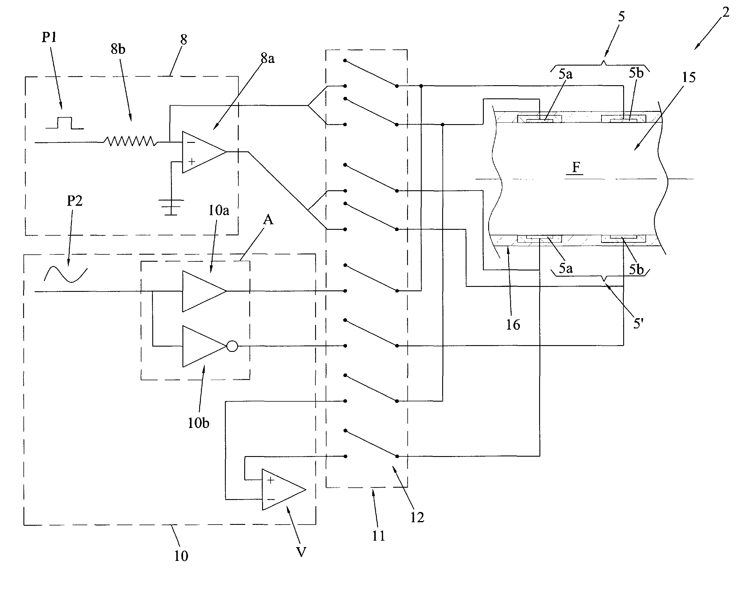
[0143]Therefore, advantageously and as previously pointed out, the embodiment 7 allows the speed, the dielectric permittivity and the electrical conductivity of the fluid F to be measured using a single device 3.

[0144]Consequently and advantageously, the device 3 is more compact and constructively simpler than the known devices that perform the same functions, both from the mechanical and electronic point of view.

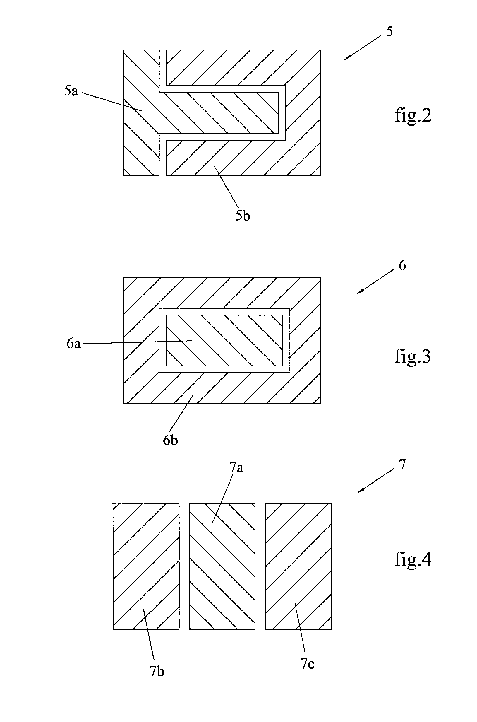
[0145]It is clear that the three zones 7a, 7b and 7c comprising each electrode 7 can be constructed with any shape, even different from that represented in the figures, maintaining in any case the functions described above.

[0146]Whatever the shape of the electrodes, they are associated with a support structure which, preferably but not necessarily, is the pipe 16 transporting the fluid F.

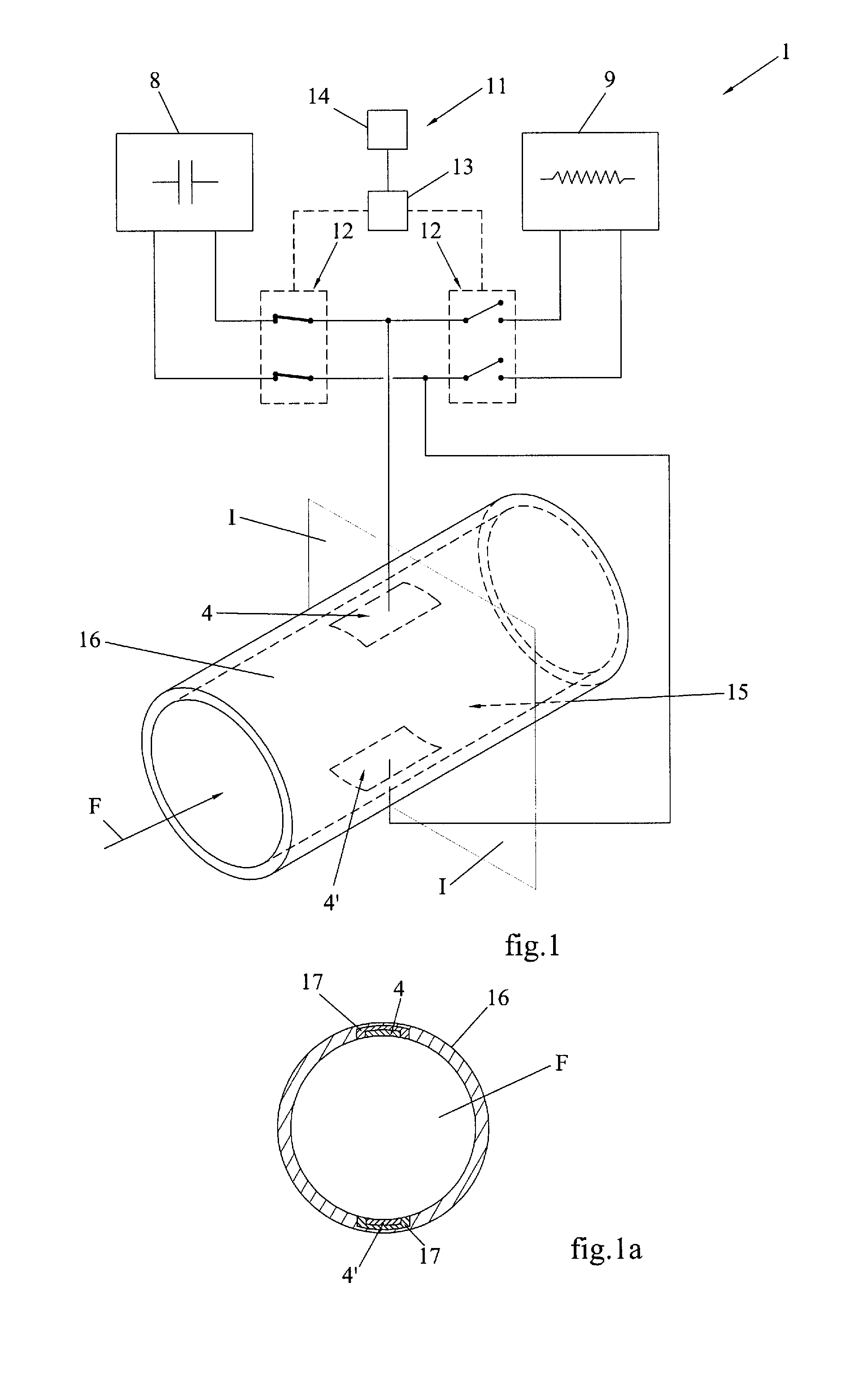
[0147]The aforesaid support structure 16 is the electric earthing of the system and defines its reference voltage.

[0148]Preferably, as can be seen in FIG. 1a, the electrodes 4, 4′ are assoc...

embodiment 6

[0193]Clearly, instead of the electrode 5 of FIG. 2, the aforesaid method could be equally applied to a device including the embodiment 6 of FIG. 3, or any other embodiment having two separate sectors.

[0194]A further embodiment of the method of the invention uses the device 3 illustrated in FIG. 6a, in which a sector of each electrode 7, 7′ includes at least two separate zones 7b and 7c of electrical contact with the fluid F.

[0195]Preferably, in this case, the method includes a third phase consisting of a sequence of measurements of only one electric quantity, dielectric permittivity or electrical conductivity, performed in sequence between each of the two corresponding pairs of zones 7b-7b and 7c-7c on the two electrodes 7, 7′, as shown in FIG. 6c.

[0196]Advantageously, the aforesaid measurements can be processed by means of a cross-correlation algorithm known per se, in order to determine the speed of the fluid using a single measuring device 3.

[0197]In addition to the measurement...

third embodiment

[0199]In particular, the device of the invention is more compact than the known devices with equivalent functionality, as it uses a single pair of electrodes to measure the dielectric permittivity of the fluid, its electrical conductivity and, in the case of the third embodiment described, also its speed.

[0200]In addition, the measurement of the conductivity and the permittivity is done by using a single pair of electrodes, so as to allow the execution of both measurements for the same zone of the fluid, with the advantage of ensuring a higher degree of precision compared to the known electrodes.

[0201]Similarly, the separation of each electrode in two sectors allows the attainment of greater measurement precision compared to the known devices, inasmuch as it enables the execution of the “four-wire method” measurement.

[0202]Upon implementation, the device and method of the invention can be subjected to further improvements or changes that, although not described herein and not repres...


PUM


Abstract

Device (2) for measuring electric parameters of a fluid (F), comprising: two measurement circuits (8, 10) for measuring, respectively, the dielectric permittivity and the electrical conductivity of the fluid (F); two electrodes (5, 5′) facing each other from opposite sides of the fluid (F); a selector system (11) for alternatively connecting the two measurement circuits (8, 10) to the electrodes (5, 5′). Each electrode (5, 5′) comprises two sectors (5a, 5b) suited to establish mutually separate electrical contact with the fluid (F) and the electrical conductivity measurement circuit (10) comprises two measurement sections (V, A) of different impedance, each one of which being connectable to a corresponding sector (5a, 5b) of each electrode (5, 5′).

Description

FIELD OF THE INVENTION[0001]The present invention regards a device for measuring the properties of dielectric permittivity and electrical conductivity of a fluid.[0002]The aforesaid device is particularly suitable for use in an apparatus for measuring the concentration and the flow rate of the different fractions or phases constituting a non-homogeneous fluid.[0003]The present invention also regards a method for executing the aforesaid measurement.BACKGROUND OF THE INVENTION[0004]As is known, the aforementioned type of apparatuses and methods are widely used in the oil production sector.[0005]In fact, the fluids extracted from oil wells are non-homogeneous mixtures of oil, salt water and gas, known in the sectors jargon as “multiphase fluids”.[0006]To determine the amount of extracted oil and, in particular, the profitability of the well, it is necessary to determine with precision not only its flow rate, but also the concentration of the different phases composing the fluid.[0007]I...

Claims


Application Information

Patent Timeline
IPC IPC(8): G06F3/042G06F3/041
CPCG01N27/226G01N27/07G01N33/2823
Inventor CALCIOLARI, PAOLOBERNARDI, STEFANO
Owner PIETRO FIORENTINI SPA
Why Eureka
Try Eureka