Measuring System for Optical Monitoring of Coating Processes

Active Publication Date: 2008-11-20
LEYBOLD OPTICS
View PDF8 Cites 7 Cited by
  • Summary
  • Abstract
  • Description
  • Claims
  • Application Information

AI Technical Summary

Benefits of technology

[0006]The task of the invention is to offer a simple measuring system for optical monitoring, suitable for steam devices and/or plasma- or io

Problems solved by technology

Nevertheless, the measuring system is relatively insensitive to mechanical distortion of the vacuum tank or local shifts o

Method used


Image

  • Measuring System for Optical Monitoring of Coating Processes
  • Measuring System for Optical Monitoring of Coating Processes

Examples


Example

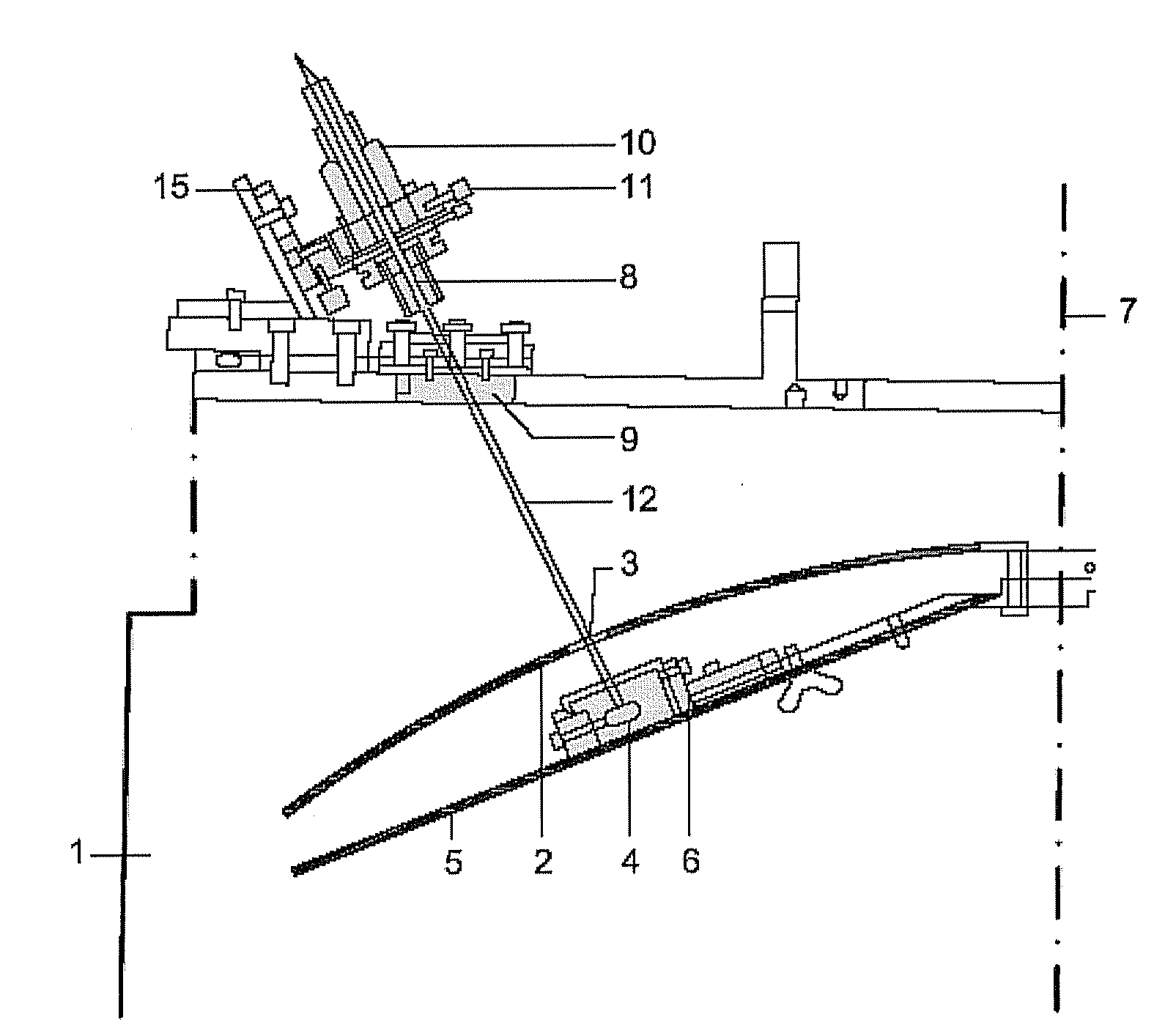
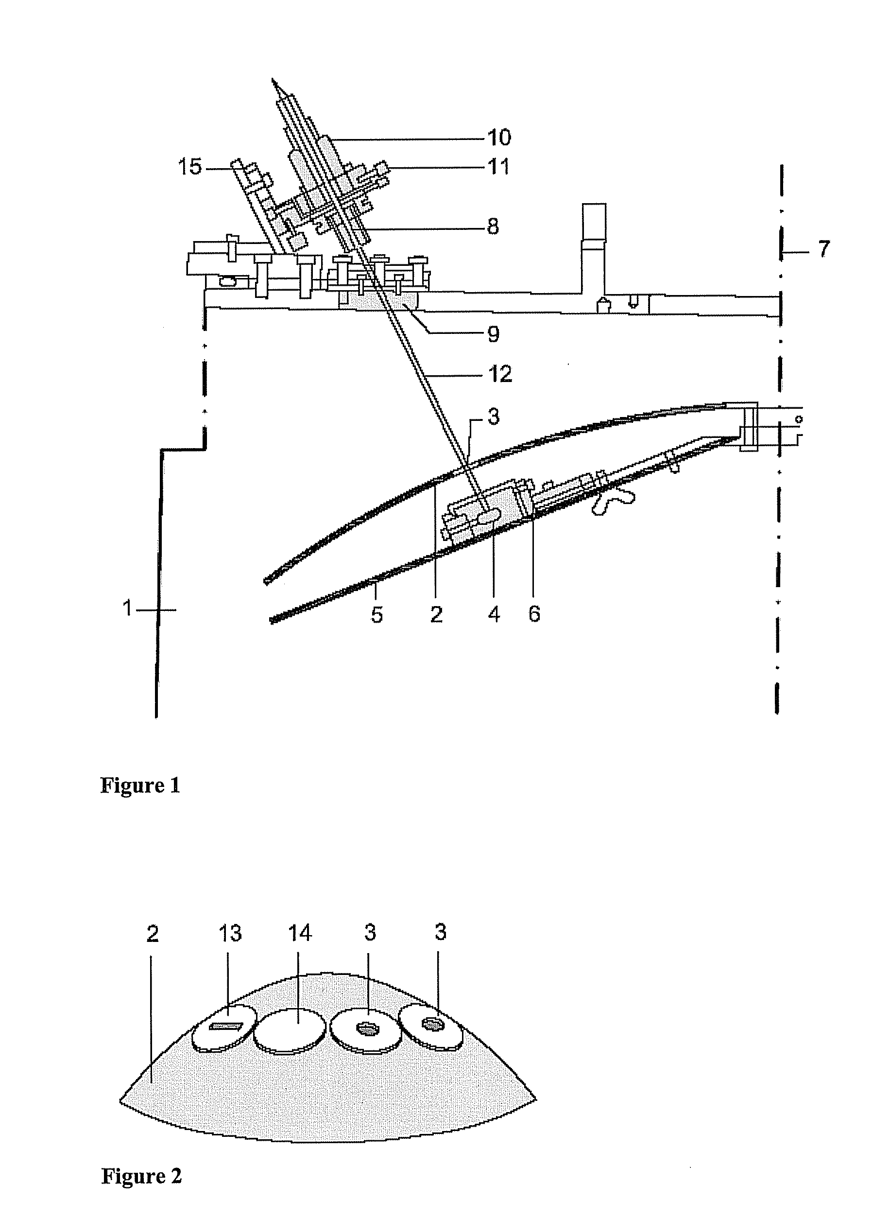
[0026]The model measuring system will be described for transmission measurement of steam-applied coated substrates 3 in a vacuum chamber 1. The substrates 3 to be coated are arranged on calotte-shaped substrate carrier 2 that revolves about an axis 7 during the coating of the substrates 3 by a coating source (not shown). A shutter 5 is mounted tightly underneath the substrate carrier 2 to optimize the layer-thickness distribution.

[0027]A broadband halogen lamp is provided as a light source 4 for the measuring system, which is located in a housing 6 and directly under the substrate carrier 2 on the shutter 5. The housing 6 is then structured so that the light of the halogen lamp can escape as a directed light beam. The shutter 5 for the layer-thickness distribution is used here at the same time as a shutter 5 for the measuring system. Power to the light source 4 is implemented with an electric cable with a vacuum.

[0028]The light-receiver unit 10 is mounted with a holding device 15 th...


PUM

PropertyMeasurementUnit
Thicknessaaaaaaaaaa
Radiusaaaaaaaaaa
Wavelengthaaaaaaaaaa

Abstract

The invention concerns a measuring system for optical monitoring of coating processes in a vacuum chamber, in which the light source is arranged inside the vacuum chamber between the substrate carrier and a shutter is arranged beneath the substrate carrier and the light-receiving unit is arranged outside the vacuum chamber in the optical path of the light source. The substrate carrier is designed to accept at least one substrate, and it can move across the coasting source in the vacuum chamber, preferably revolving about an axis, whereby the substrate or substrates cross(es) the optical path between the light source and the light-receiving unit for transmission measurement, and the shutter shades a measurement area across the coating source.

Description

TECHNICAL FIELD OF INVENTION[0001]The invention concerns a measuring system for optical monitoring of coating processes in a vacuum chamber, particularly for the measurement of layer thicknesses of coatings applied to substrates during the coating process, that comprises a system for light injection and a light-receiving device.BRIEF DESCRIPTION OF RELATED ART[0002]For substrates that are coated with thin layers on the size scale of light wavelengths to achieve prescribed optical properties, the layers must be applied with high uniformity and exact layer thicknesses to achieve the prescribed transmission or reflection properties. The layer thickness is determined by transmission and reflection measurements and takes place in situ in order to control the layer thickness precisely To measure such thin layer thicknesses, photometers are frequently used that include a monochromatic transmission or reflection signal of the coated substrate in a measuring phase and a reference signal of t...

Claims


Application Information

Patent Timeline
IPC IPC(8): G01B11/06
CPCG01B11/0683C23C14/547G01B11/06C23C14/54
Inventor ZOLLER, ALFONSHAGEDORN, HARROKLUG, WERNER
Owner LEYBOLD OPTICS
Why Eureka
Try Eureka