
Microcontroller network diagnostic system

a microcontroller and network diagnostic technology, applied in the field of industrial networks, can solve problems such as network error rates, drive up maintenance costs, and downtime of devices connected to the network or signal bus, and achieve the effect of facilitating prediction of failures

Active Publication Date: 2014-03-04
WOODHEAD IND INC
View PDF12 Cites 5 Cited by
  • Summary
  • Abstract
  • Description
  • Claims
  • Application Information

AI Technical Summary

Benefits of technology

The network diagnostic device offers two modes of operation: an Individual Measurement mode and a Network Health mode. The Network Health mode simplifies troubleshooting of a DN installation by providing a single overall network health status based on the measurement values of all network parameters. The status indicates whether the network is operating within the desired parameters or whether it needs attention. The device allows users to quickly identify the specific problem in the network. The system also directs users to the specific fault sources, reducing the time required to isolate the problem. The device software reduces the number of measures that users need to review, making it easier to identify and fix network issues. Overall, the network diagnostic device improves efficiency in identifying and troubleshooting network issues.

Problems solved by technology

Invalid bit transmissions increase network error rates, drive up maintenance costs, and may result in down time for the devices connected to the network or signal bus.
Existing DeviceNet network diagnostic devices have limited processing power and, therefore, typically collect only frame-level diagnostic information for storage in local memory.
This prevents real-time analysis and network fault prediction since these devices do not interface with external networks and must first collect sufficient data prior to making it available (e.g., via a USB port connection).
Furthermore, collection of frame-level information does not provide sufficient detail for waveform analysis that is needed to validate bit-level transmissions from particular network nodes.

Method used


Image

  • Microcontroller network diagnostic system
  • Microcontroller network diagnostic system
  • Microcontroller network diagnostic system

Examples


Embodiment Construction

[0036]The following examples further illustrate the invention but, of course, should not be construed as in any way limiting its scope.

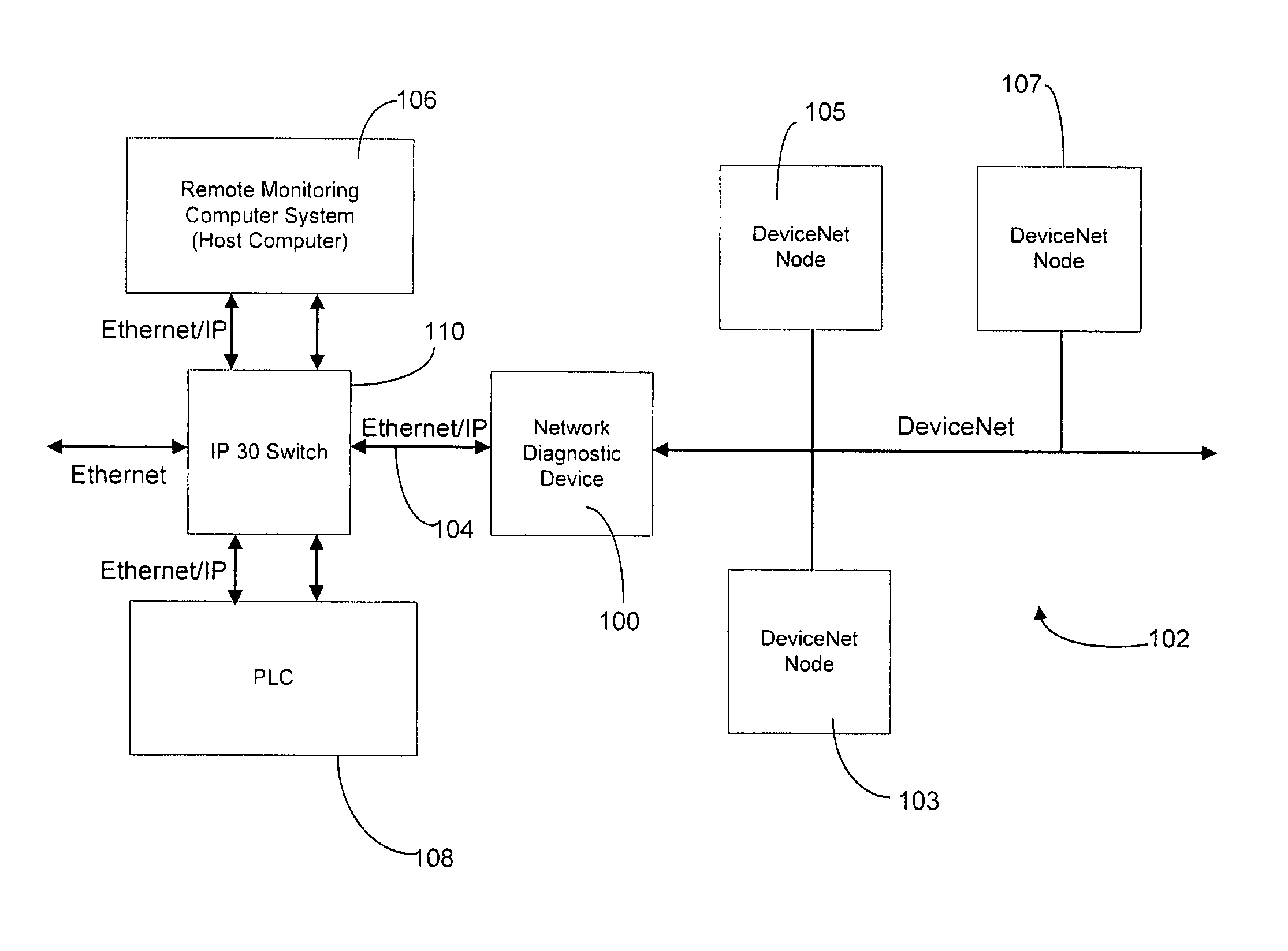
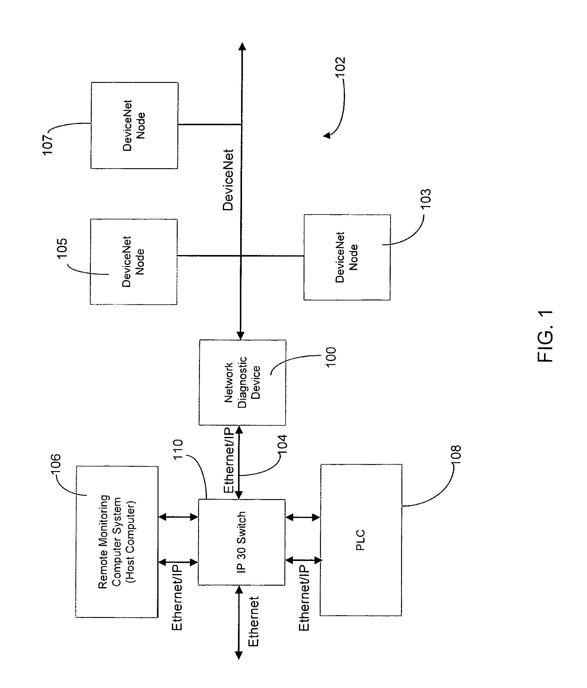
[0037]Turning to FIG. 1, an embodiment of a network environment including a network diagnostic device for monitoring signal-level status of a Controller Area Network (CAN)-based network, such as a DeviceNet network, is shown. Although the following description provides an exemplary embodiment for monitoring signal-level (or bit-level) status of a DeviceNet network, those skilled in the art will appreciate that the following description is applicable to diagnosing the status of CAN-based networks in general, as well as other networks operating in accordance with a predetermined network specification, including Ethernet-based networks.

[0038]The network diagnostic device 100 is a passive device that continuously monitors a plurality of bit-level waveform parameters associated with a DeviceNet network 102, including the data transmitted by a plurality of...


PUM


Abstract

A network diagnostic device is provided, which comprises a passive real-time measurement tool that is useful for, among other things, expediting fault identification, isolation, and repair of a communication network or bus. The device also facilitates prediction of failures by identifying marginal operating conditions. The device analyzes data flowing through the communication network, including through an analysis of variations in bit waveform shape carried by the network physical interconnect media. In one embodiment, an implementation of the network diagnostic device is particularly useful in a DeviceNet-compatible network or, more generally, a Controller Area Network (CAN). The device identifies faults by comparing measurements made on the actual DeviceNet bus with worst-case acceptable criteria. The device interfaces with a remote monitoring computer via an Ethernet compatible medium to display parsed bit-level waveforms, network warnings and errors, as well as an overall network health index.

Description

CROSS-REFERENCE TO RELATED APPLICATIONS[0001]This patent application claims the benefit of U.S. Provisional Patent Application No. 61 / 101,059 filed Sep. 29, 2008, which is incorporated herein by reference in its entirety, including without limitation all drawings and figures therein.FIELD OF THE INVENTION[0002]This invention relates generally to the field of industrial networks and more specifically to controller area network diagnostic systems.BACKGROUND OF THE INVENTION[0003]Digital communication signals have international standards that define minimum signal thresholds for a binary one, or a high condition, and maximum signal thresholds for a binary zero, or a low condition. A standard for a particular type of communication signal typically also defines a transition time and / or voltage threshold as a reference, and specifies a time delay after the transition event during which to measure the data voltage in order to determine the validity of a particular bit. Therefore, if the si...

Claims


Application Information

Patent Timeline
Patent Type & Authority Patents(United States)
IPC IPC(8): G06F13/00
CPCH04L2012/40215H04L12/40H04L43/0805H04L41/06
Inventor ORTON, TREVORTURNBULL, WILLIAMKAUZUNOVICH, SERGEI
Owner WOODHEAD IND INC
Learn More