Polyurethane panel

a polyurethane and panel technology, applied in the field of polyurethane panels, can solve the problems of requiring additional components, affecting the quality of polyurethane panels, so as to reduce the risk of fracturing and/or breaking

Inactive Publication Date: 2014-03-11
SCHOOTS NICOLA +1
View PDF15 Cites 32 Cited by
  • Summary
  • Abstract
  • Description
  • Claims
  • Application Information

AI Technical Summary

Benefits of technology

[0009]The coated polyurethane panel according to the present invention is advantageous as it has substantially improved characteristics which may be selected from, but not limited to, strength, compressibility, flexibility or resistance. Such improved characteristics substantially reduces the fracturing and / or breakage of coated panels when formed into shapes without first requiring that the panel be heated to deformation temperatures in comparison to uncoated panels. This therefore increases the applicability of the coated polyurethane panel according to the invention when compared to uncoated panels.
[0026]Even further preferably, the coated panel of the invention is substantially reduced from fracturing and / or breaking when the coated panel is substantially formed without first heating the panel to a deformation temperature.

Problems solved by technology

It is has been found that the resin material used in the manufacture of wood chip or composite-type panels is carcinogenic.
Such panels are further disadvantageous in that they are relatively heavy and require additional components in order to be moisture resistant.
While water and fire resistant, fibre cement panels are disadvantageous in that they are typically very heavy, where only thick panels have good impact resistance.
Thin fibre cement panels are very fragile and must be handled carefully to avoid chipping and breakage.
While laminating or veneering polyurethane panels with, for example, melamine or plywood, improves strength and rigidity, this is at a cost to flexibility and, consequently, the applicability of panels.

Method used


Image

  • Polyurethane panel
  • Polyurethane panel
  • Polyurethane panel

Examples


example 1

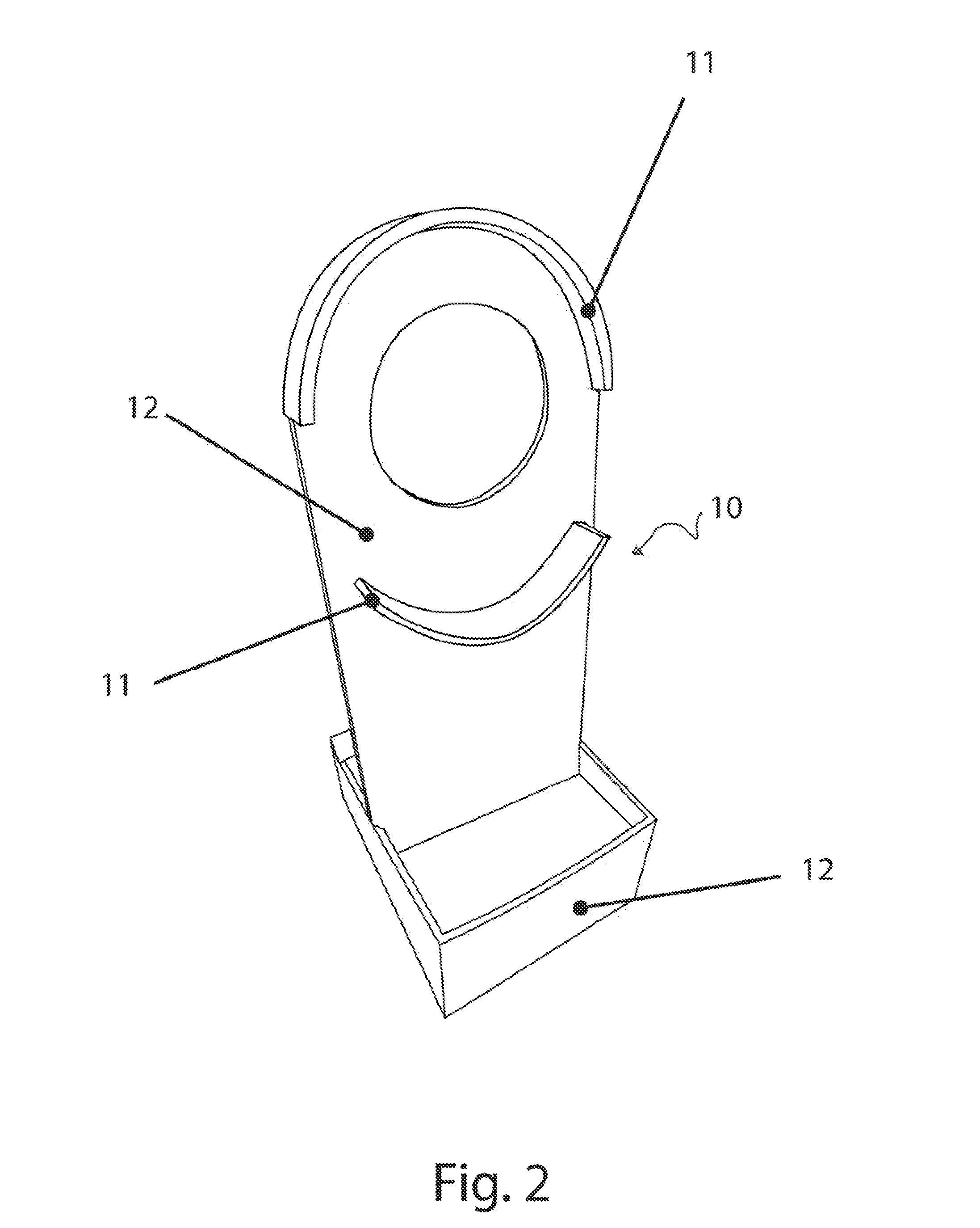
[0113]In one exemplary embodiment, FIG. 2 shows a water feature (10) made from an embodiment of the coated polyurethane panel according to the invention. Preferably, the water feature (10) according to this embodiment is first cut from Aptane™ P258 / B900 Multipanel. Structures requiring curves (11) are deformed into shape using heat. The water feature (10) is then assembled by fixing flat structures (12) and curved structures (11) together using appropriate adhesives and fixings. The assembled water feature is then sprayed with Tuff Stuff™ polyurethane elastomer and the coating allowed to set.

[0114]Alternatively, the water feature (10) according to this embodiment may be cut from Aptane™ P258 / B900 Multipanel, where structures requiring curves (11) are deformed into shape using heat. The separate pieces (11 and 12) are then sprayed with Tuff Stuff™ polyurethane elastomer, and the coating allowed to set. The water feature (10) can be shipped flat-packed which reduces transportation cos...

example 2

[0116]In another exemplary embodiment, FIGS. 3 and 4 show a planter boxes (20 and 30, respectively) made from an embodiment of the coated polyurethane panel according to the invention.

[0117]Similarly to Example 1, pieces which form the planter box (20 or 30) are cut from a sheet of Aptane™ P258 / B900 Multipanel, preferably 25 mm thick. Walls of the planter boxes (21 and 31, respectively) are assembled using appropriate fixings and adhesives. According to the embodiments shown, the planter boxes may include a top edge (22 and 32, respectively) made from 100 mm×500×5 mm thick Aluminium Angle which is mitred and welded. The Aluminium Angle adds strength to the top edge as well as providing an aesthetically pleasing finish. The boxes are then sprayed with at least a 1 mm thick layer of Tuff Stuff™ polyurethane elastomer.

[0118]Assembly of the planter boxes (20 or 30) can occur onsite using coated polyurethane panel pieces shipped flat-packed and appropriate adhesives and fixings as descri...

example 3

[0120]In yet a further exemplary embodiment, FIGS. 5 and 6 show housing made from an embodiment of the coated polyurethane panel according to the invention. The unit (50) (or ‘Pod’) shown can be used to construct modular (‘Podula’) housing in which several Pods are attached together. Such housing can be either temporary or permanent.

[0121]The embodiment of the Pod (50) shown includes the following components:[0122]An Aptane™ P258 / B900 Multipanel of 1200 mm×2400 mm used as the floor (51).[0123]1200 mm×2400 mm Aptane™ P258 / B900 Multipanels used to form the walls (52, 55 and 56). The tip of the arc (53) is 2400 mm high, and 6 m in length.[0124]Door frame and supports (54) are fabricated from stainless steel.[0125]Support angle to base (57) is fabricated from 50 mm×50 mm×1 mm galvanised steel.

[0126]The back (55) and front (56) walls are preferably fabricated 25 mm thick panels, whereas the floor (51) and side walls (52) are preferably fabricated from 16 mm thick panels. The panels may b...


PUM

PropertyMeasurementUnit
temperatureaaaaaaaaaa

Abstract

Building panels are ubiquitous in the building industry and are used to form walls, doors or other partitions, either of a structural or non-structural nature. Polyurethane can be formed into a panel which is rigid and can function in the same manner as conventional panels formed from wood and other material. The panel is able to be cut, screwed, drilled, painted, laminated or veneered. While laminating or veneering polyurethane panels with, for example, melamine or plywood, improves strength and rigidity, this is at a cost to flexibility and, consequently, the applicability of panels. The invention defined herein therefore relates to an improved polyurethane panel which overcomes the disadvantages of those which have gone before. The panel of the invention finds particular use, although not exclusive use, in building and construction.

Description

FIELD OF THE INVENTION[0001]The present invention relates to an improved polyurethane panel. The panel finds particular use, although not exclusive use, in building and construction.BACKGROUND[0002]Building panels are ubiquitous in the building industry and are used to form walls, doors or other partitions, either of a structural or non-structural nature. Building panels are conventionally made from wood, most commonly plywood, wood chips or a composite material such as medium density fibreboard (MDF).[0003]Engineered wood products, such as MDF, are made by breaking down hardwood or softwood residuals into wood fibres, and combining the fibres with wax and a resin binder. Panels are formed therefrom by applying high temperature and pressure. It is has been found that the resin material used in the manufacture of wood chip or composite-type panels is carcinogenic. Such panels are further disadvantageous in that they are relatively heavy and require additional components in order to b...

Claims


Application Information

Patent Timeline
Patent Type & Authority Patents(United States)
IPC IPC(8): B32B27/40B05D5/00C08G18/00
CPCB32B27/06C08G18/7664C08G18/6685C09D175/12Y10T428/31554
Inventor SCHOOTS, NICOLASCHOOTS, STEVEN
Owner SCHOOTS NICOLA
Why Eureka
Try Eureka