Supercharge Your Innovation With Domain-Expert AI Agents!

Multi-level output comparator

a comparator and output technology, applied in the direction of amplifiers, dc-amplifiers with dc-coupled stages, modulation, etc., can solve the problems of limiting the frequency at which comparisons may be performed, flash adcs, and a large number of dedicated comparators

Inactive Publication Date: 2014-03-11
DIALOG SEMICONDUCTOR GMBH
View PDF4 Cites 0 Cited by
  • Summary
  • Abstract
  • Description
  • Claims
  • Application Information

AI Technical Summary

Benefits of technology

Enables high-speed, high-frequency operation with multiple outputs for precise deviation indication from a reference voltage, reducing the need for multiple comparator circuits and enhancing speed and efficiency.

Problems solved by technology

Such comparators suffer, however, from lengthy recovery times from saturation of the operational amplifiers, thereby limiting the frequency at which comparisons may be performed.
Furthermore, such comparators only provide a single output, i.e. a single comparison, with no indication on how much the input voltage deviates from the reference voltage.
Flash ADCs are disadvantageous in that they require a large number of dedicated comparators.
Furthermore, flash ADCs may have limited speed (as a result of the limited speed of the plurality of comparators).

Method used


Image

  • Multi-level output comparator
  • Multi-level output comparator
  • Multi-level output comparator

Examples


Embodiment Construction

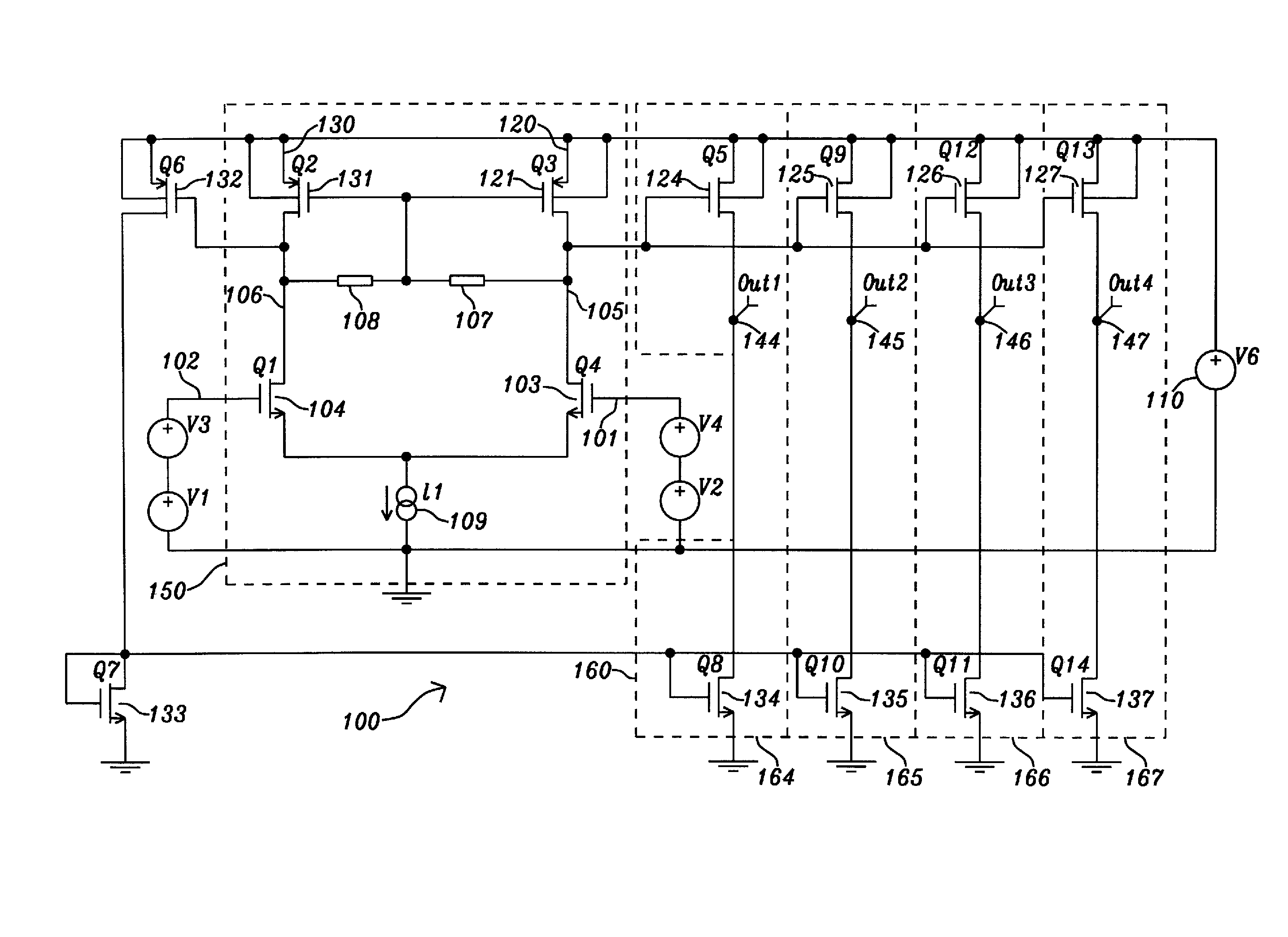
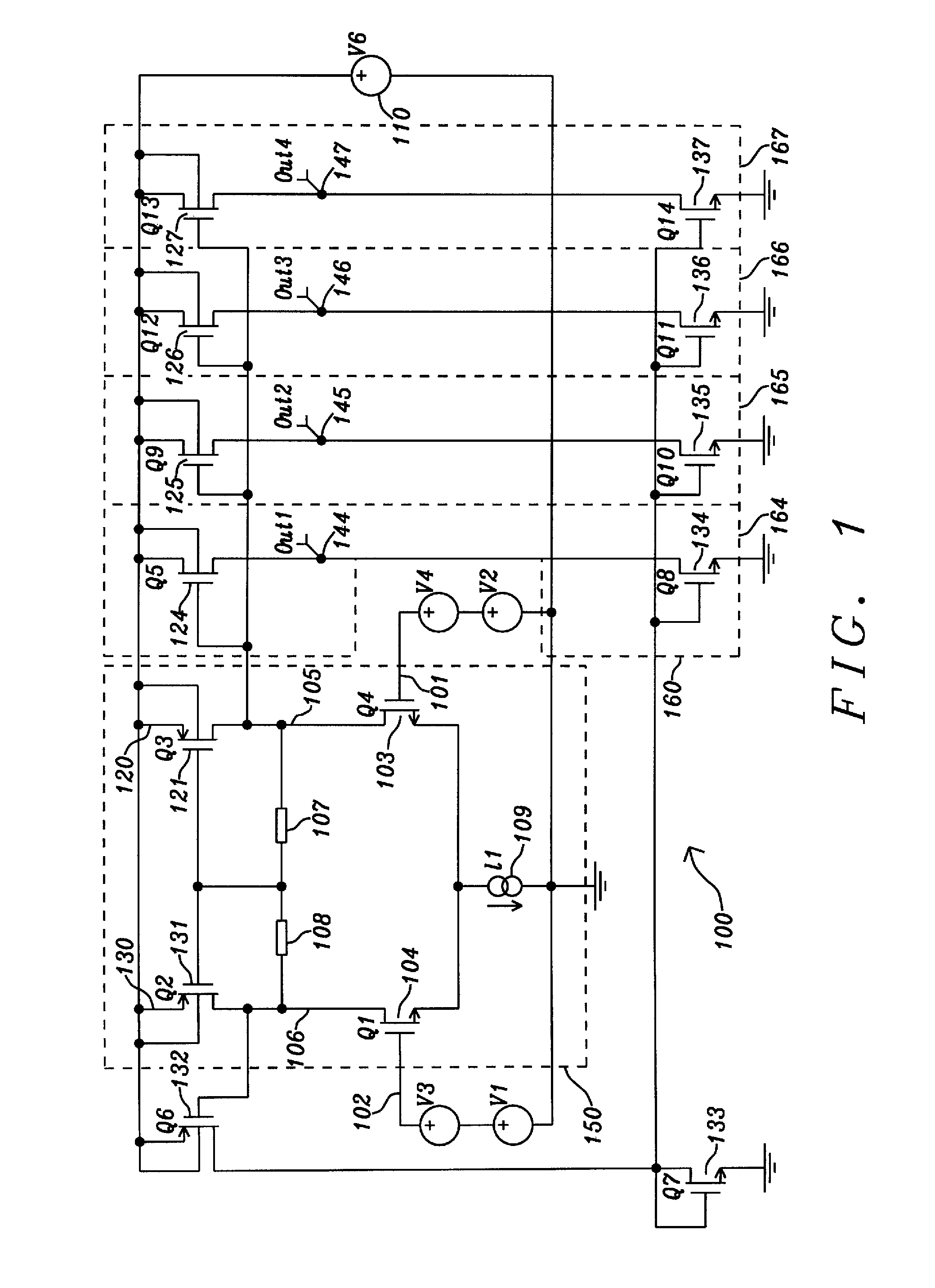
[0028]FIG. 1 shows a circuit diagram of an example multi-level comparator 100. The comparator 100 comprises a gain unit 150 at its input. The gain unit 150 may be used to amplify / attenuate a voltage difference at the input of the gain unit 150 (i.e. the voltage difference between the input voltage Vin at a first input port 101 and the reference voltage Vref at a second input port 102), thereby yielding a voltage difference at the output voltage ports of the gain unit 150 (i.e. the voltage difference between the first output voltage at a first output voltage port 105 and the second output voltage at a second output voltage port 106). The example gain unit 150 of FIG. 1 is implemented as a differential amplifier comprising the (FET, e.g. MOSFET or CMOS) transistors 103, 104 and the resistors 107, 108.

[0029]In addition to providing amplification / attenuation, the gain unit 150 of FIG. 1 may be used to provide a differential current at a first output transistor 121 (i.e. at the first out...


PUM


Abstract

The present document relates to a method and system for determining the voltage level of an input signal compared to a reference voltage, providing a plurality of level indications regarding an input voltage with respect to a reference voltage. The multi-level comparator comprises an input stage converting the input voltage into a first current and converting the reference voltage into a second current; and a plurality of comparator stages, each comprising a first current amplification unit amplifying the first current with a first gain, a second current amplification unit amplifying the second current with a second gain, and an output port providing an indication whether the first comparator current is smaller or larger than the second comparator current; wherein respective ratios of the first gain and the second gain of the plurality of comparator stages are different.

Description

BACKGROUND OF THE INVENTION[0001](1) Field of Invention[0002]The present document relates to a multi-level output comparator. In particular, the present document relates to a method and system for determining the voltage level of an input signal compared to a reference voltage.[0003](2) Description of the Prior Art[0004]Comparators are electronic devices which compare an input voltage with a reference voltage (or an input current with a reference current), and provide at their output an indication which of the two voltages (or currents) is greater. Comparators may be designed based on operational amplifiers with a particularly high gain. Such comparators suffer, however, from lengthy recovery times from saturation of the operational amplifiers, thereby limiting the frequency at which comparisons may be performed. Furthermore, such comparators only provide a single output, i.e. a single comparison, with no indication on how much the input voltage deviates from the reference voltage.[...

Claims


Application Information

Patent Timeline
Patent Type & Authority Patents(United States)
IPC IPC(8): H03F3/45H02M11/00
CPCH03K5/2481
Inventor KNOEDGEN, HORST
Owner DIALOG SEMICONDUCTOR GMBH
Features
  • R&D
  • Intellectual Property
  • Life Sciences
  • Materials
  • Tech Scout
  • Unparalleled Data Quality
  • Higher Quality Content
  • 60% Fewer Hallucinations
Learn More