Process and apparatus for localized coating of assembled cascade impactor particle collection surfaces
a cascade impactor and particle collection technology, applied in the direction of superimposed coating process, liquid/solution decomposition chemical coating, instruments, etc., can solve the problems of no reliable means to avoid interference with chemical assays, poor control of the total amount of coating materials applied,
- Summary
- Abstract
- Description
- Claims
- Application Information
AI Technical Summary
Benefits of technology
Problems solved by technology
Method used
Image
Examples
example 1
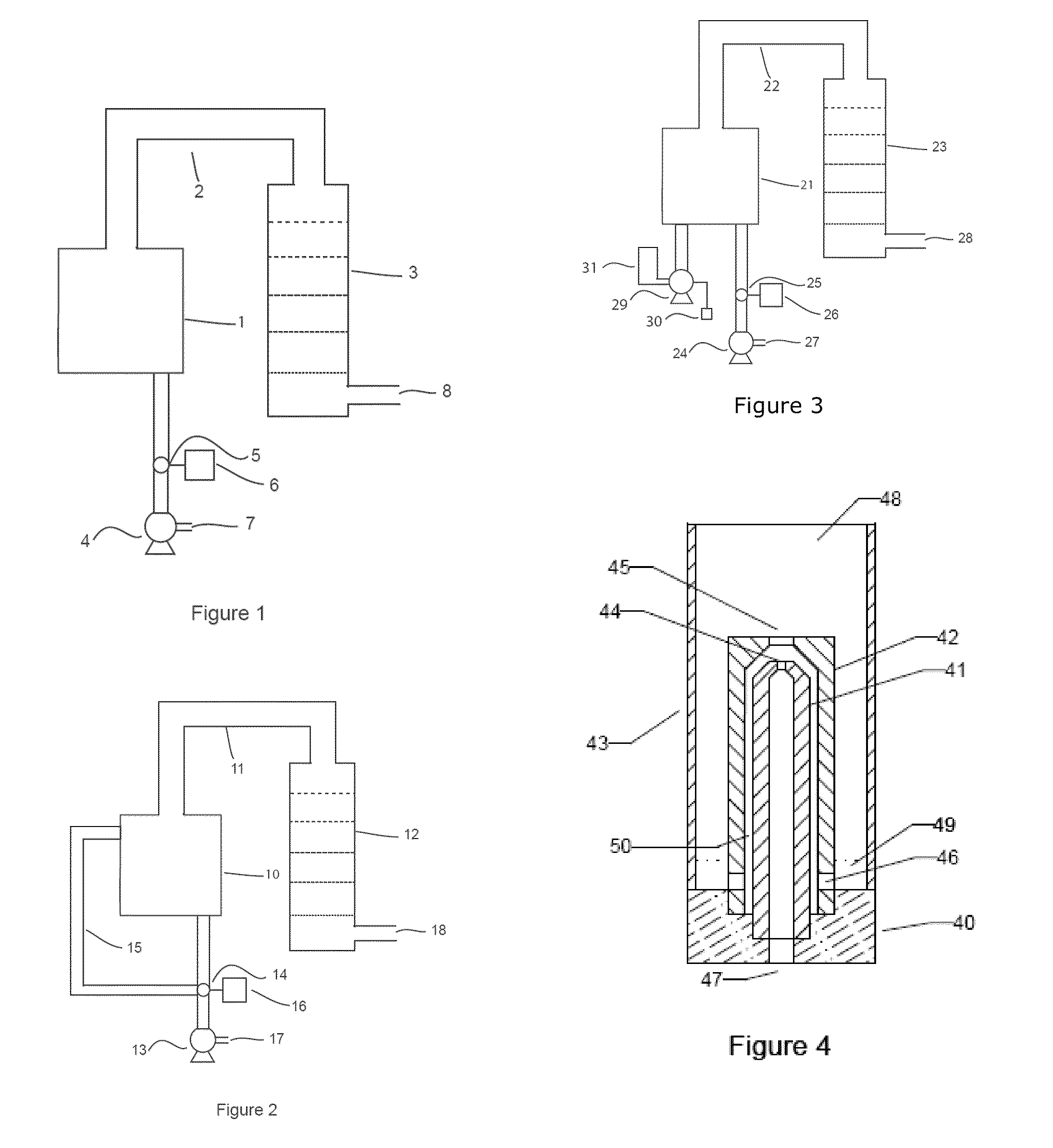
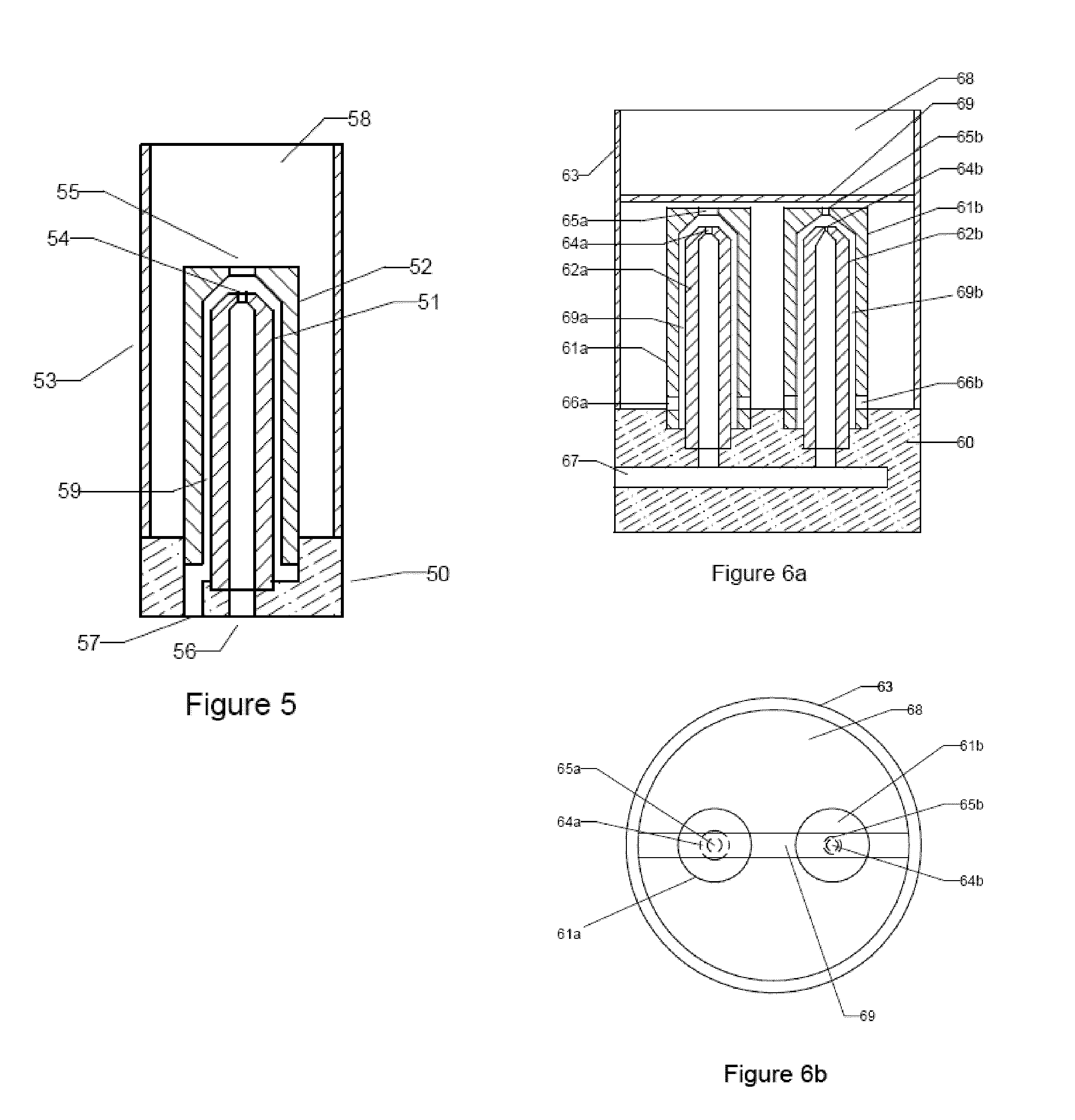
[0139]An embodiment of the invention with two atomizer heads was constructed. The atomizer heads were configured with a particle impaction surface as shown and described in FIG. 6. The dimensions of the first orifices of the two atomizer heads were 0.0178 and 0.0410 inches, respectively. For both atomizer heads, the ratio of the diameter of the second orifice to the first orifice was about 2.0. The dimension of the liquid channel in the two atomizer heads was about 0.069 inches. Four holes were used in each outer sleeve to allow the liquid coating material to be aspirated into the atomizers. The impaction surface was located 0.035 inches away from the exits of the second orifices. A solution of silicone Antifoam (Dow Corning 1520) was prepared as a 1:10 dilution in water and labeled with 0.01% ammonium fluorescein to assist in visualization and chemical analysis. 3.2 ml of the solution was added to the atomizer chamber.
example 2
[0140]An eight-stage Andersen cascade impactor (Westech Instruments, Atlanta, Ga.) was assembled with clean, uncoated collection plates according to the manufacturer's instructions. The atomizer heads in the embodiment described in Example 1 were operated at 8.2 psi for about 1.5 minutes. At that pressure, the total airflow was approximately 30 lpm. The coating aerosol droplets were directed to the inlet of the Andersen impactor. The outlet of the impactor, which in normal operation according to the manufacturer's instructions is connected to a vacuum source, was left open to the atmosphere to allow the coating aerosol droplets to flow through the device. Following atomization of the coating material, clean, dry air was passed through the impactor for 8 minutes to evaporate residual solvent and dry the coating material.
example 3
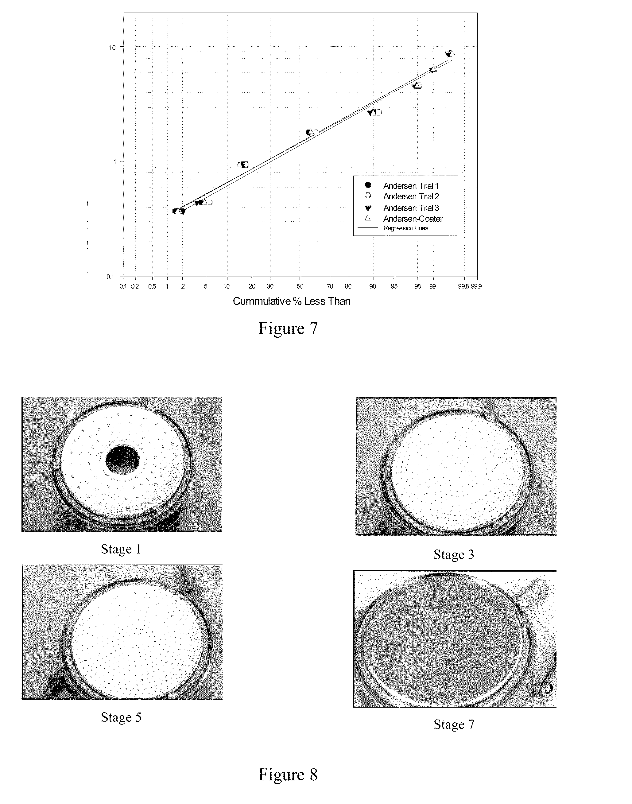
[0141]The impactor was disassembled and the particle collecting plates were visually observed and photographed to ascertain the uniformity of the coating material in the particle collecting regions of the impactor plates. The amount of coating material deposited was determined chemically by assaying the fluorescein tracer with a Turner Biosystems Picofluor fluorometer (Sunnyvale, Calif.). Visual inspection showed uniformity of the deposited coating material in the particle collecting regions of the impactor plate. Table 1 gives the total amount of grease deposited on each of the stages. The results show a sufficient amount of material deposited in the particle collecting regions of each stage.
[0142]
TABLE 1Amount of Grease [mg] Deposited on Each ParticleCollection Surface of the Andersen Cascade ImpactorQuantity of AntifoamStage No.Deposited [mg]00.2710.2920.1530.2740.4752.1861.4170.67
PUM
| Property | Measurement | Unit |
|---|---|---|
| diameter | aaaaa | aaaaa |
| diameter | aaaaa | aaaaa |
| diameter | aaaaa | aaaaa |
Abstract
Description
Claims
Application Information
 - R&D
- Intellectual Property
- Life Sciences
- Materials
- Tech Scout
- Unparalleled Data Quality
- Higher Quality Content
- 60% Fewer Hallucinations
Browse by: Latest US Patents, China's latest patents, Technical Efficacy Thesaurus, Application Domain, Technology Topic, Popular Technical Reports.
© 2025 PatSnap. All rights reserved.Legal|Privacy policy|Modern Slavery Act Transparency Statement|Sitemap|About US| Contact US: help@patsnap.com


