
Temperature controlled showerhead

a temperature control and shower head technology, applied in the direction of coatings, chemical vapor deposition coatings, electric discharge tubes, etc., can solve the problems of reduce wafer-to-wafer non-uniformity, and achieve accurate and stable temperature control , improve heat dissipation, the effect of fast respons

Active Publication Date: 2014-03-18
NOVELLUS SYSTEMS
View PDF58 Cites 34 Cited by
  • Summary
  • Abstract
  • Description
  • Claims
  • Application Information

AI Technical Summary

Benefits of technology

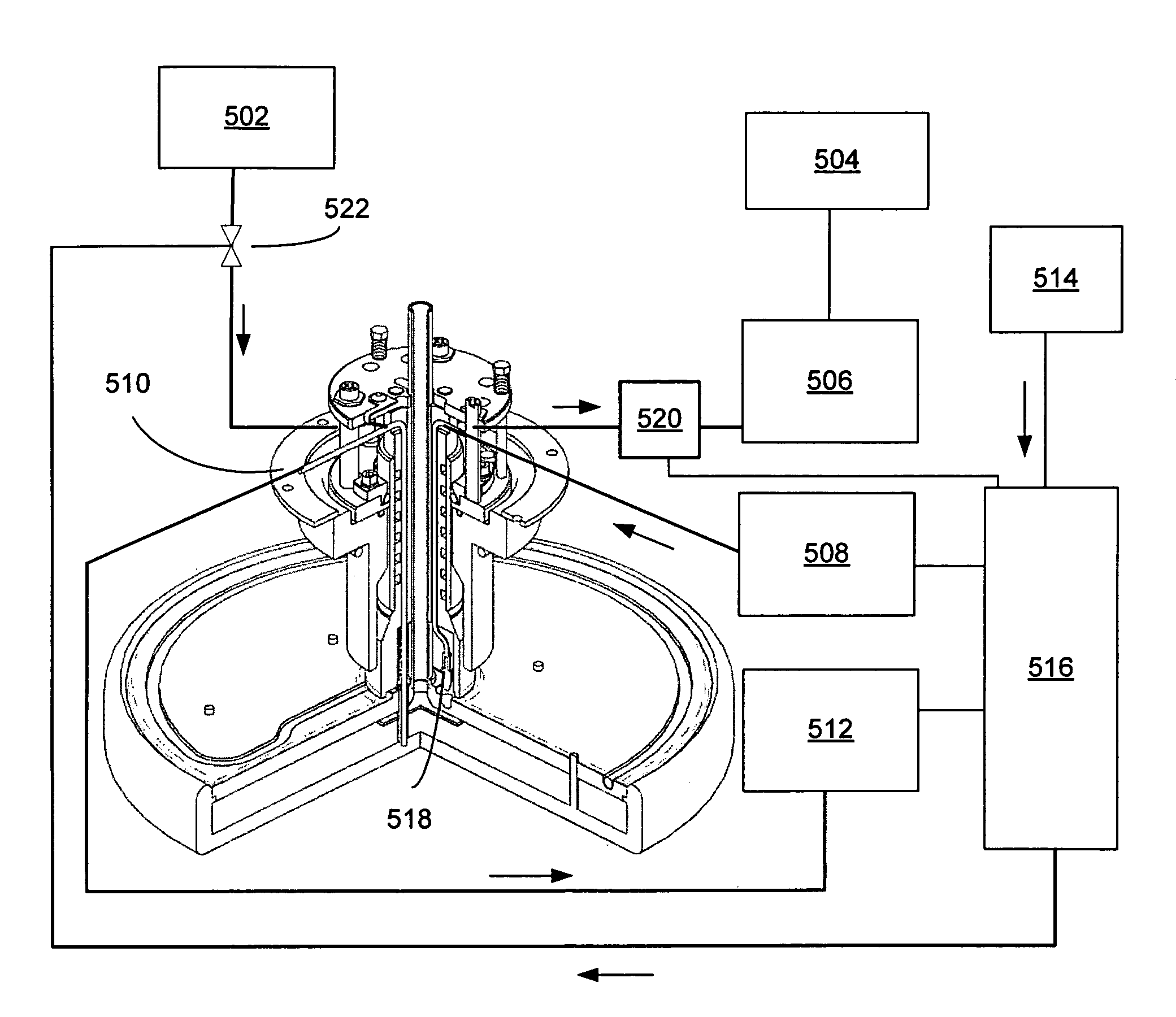
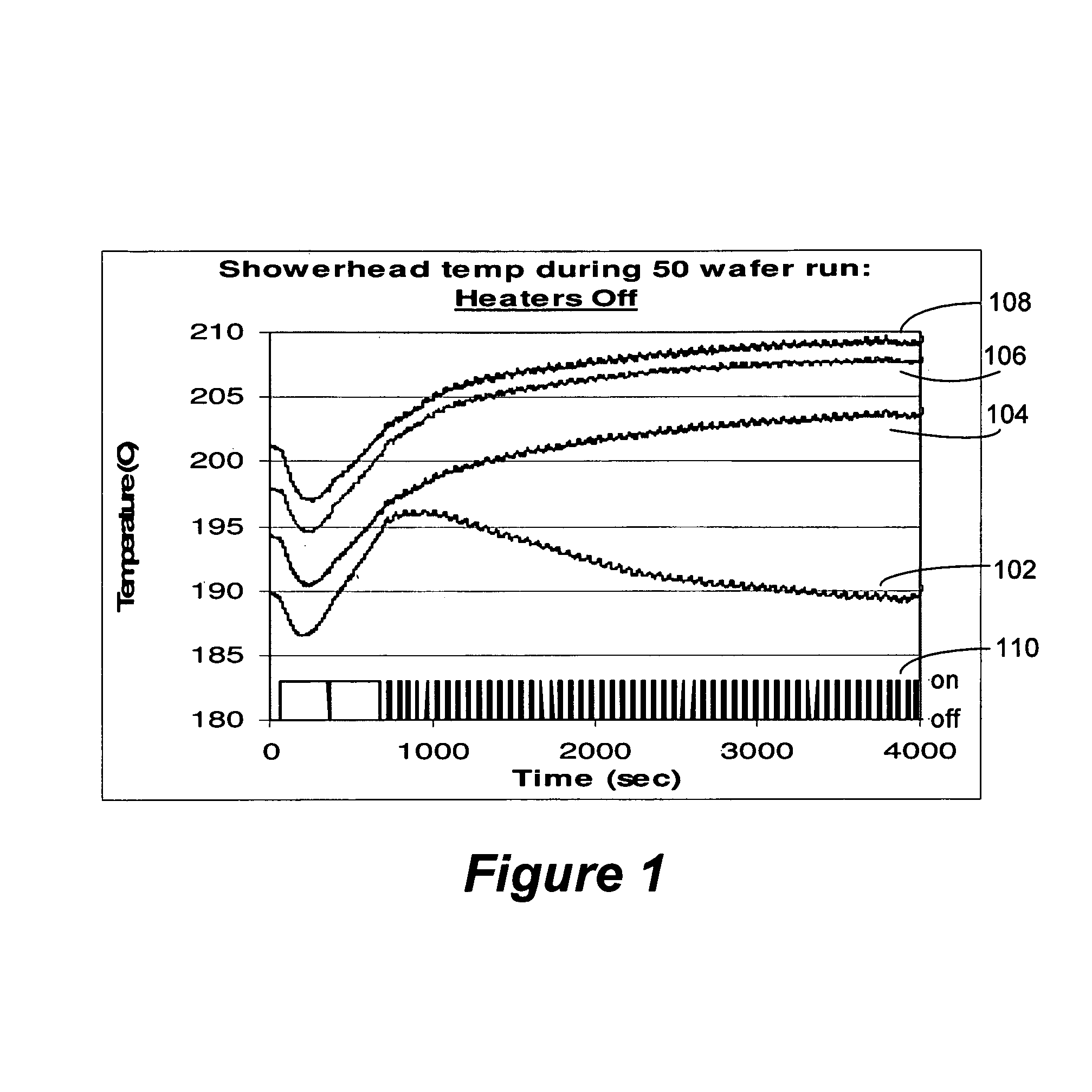
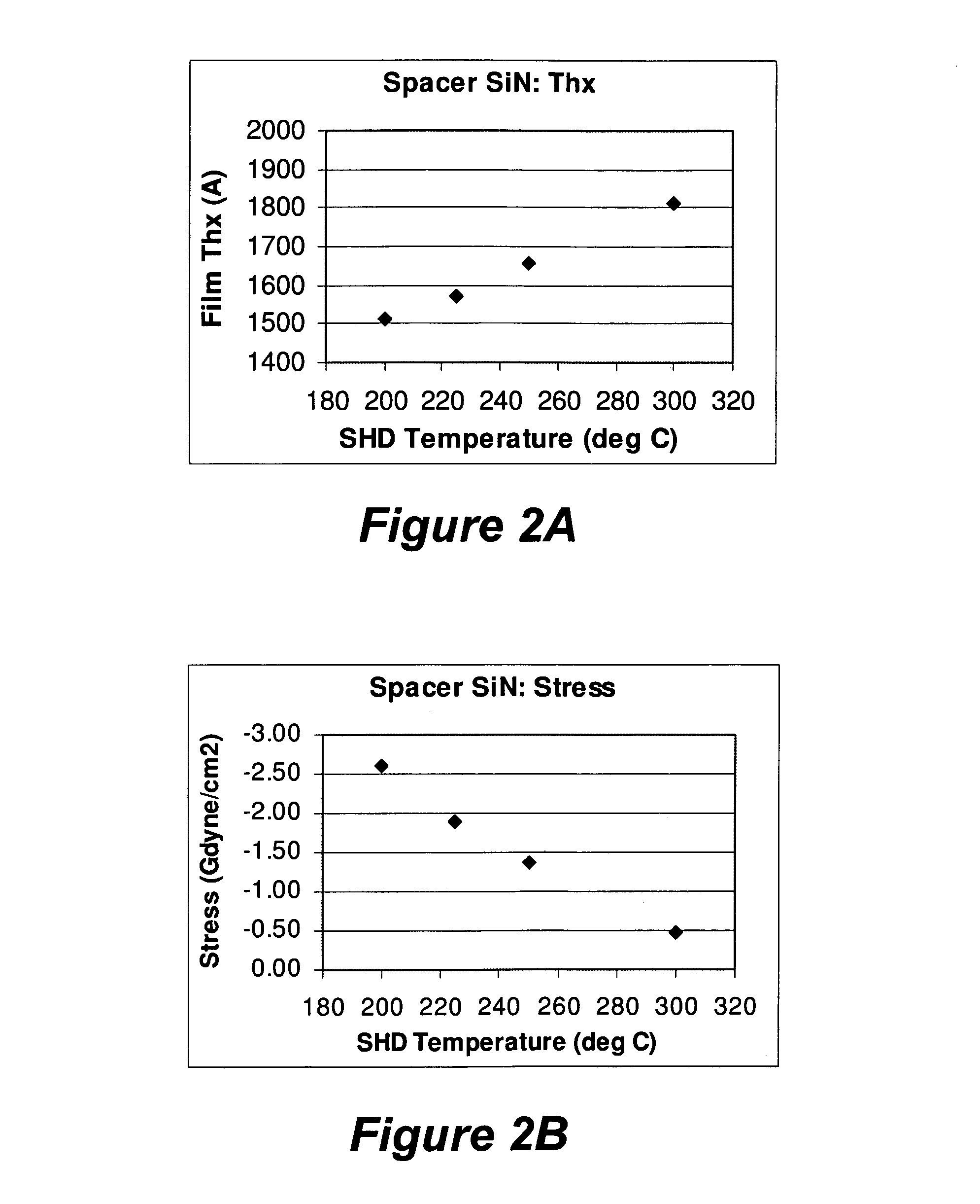
[0007]A temperature controlled CVD showerhead and temperature control system with enhanced heat dissipation enable accurate and stable temperature control with fast response. Accurate temperature control reduces wafer-to-wafer non-uniformity within continuous batch processing and from batch to batch. The enhanced heat dissipation and heater enable quick recovery to the temperature set point when changes in the operating environment perturb the system. Increased heat dissipation is achieved by increased conduction through the showerhead stem, additional convective cooling using a fluid in a fluid passageway and increased radiation from a back plate. The temperature control system also includes a heat exchanger that serially cools the convective cooling fluid flowing in the showerhead fluid passageway. In addition, the showerhead temperature may provide an additional parameter for process optimization.
[0009]The stem houses a channel through which reactant and carrier gases flow to the face plate, where the gases are distributed through holes or perforations in the face plate. A baffle plate or some other distribution device may be located between the end of the gas channel and the face plate to help distribute the gas evenly. The stem also houses a convective cooling fluid passageway through which cooling fluid may flow to cool the showerhead. The fluid passageway is constructed so that it is isolated from the reactant channel in the stem carrying reactant and carrier gases to the showerhead. The convective cooling fluid enters the stem at an inlet and may exit the stem through one or more exit channels. In the stem, the inlet or the outlet channel or both channels of the passageway may follow a helical path or some other tortuous path designed for conductive heat transfer between the fluid and the surface. The cooling fluid may be clean dry air (CDA), argon, helium, nitrogen, hydrogen, or a mixture of these. Though not preferred, water and oil based liquid coolant may be used as the convective cooling fluid. Particularly, the CDA may be supplied by fab facilities at a pressure of about 50-100 psi. The CDA may also be cooled by a heat exchanger connected to more than one showerhead serially. Serial cooling means that the CDA may be supplied to various showerheads with intermediate cooling by the heat exchanger. For example, the CDA may be supplied to a first showerhead, cooled by the heat exchanger, supplied to a second showerhead, cooled by the heat exchanger, supplied to a third showerhead, cooled by the heat exchanger, supplied to a fourth showerhead, cooled by the heat exchanger, and exhausted. This arrangement minimizes the amount of air used and also ensures a low temperature of the exhaust, eliminating safety hazards.
[0010]The face plate contains holes or perforations through which gas reactants flow to the wafer. The face plate may have various configuration of hole patterns of difference sizes. The face plate may be removably attached to the back plate so as to facilitate cleaning or changing hole patterns. The temperature of the face plate may be measured by a thermocouple in physical and thermal contact with the face plate, or by other means that are less susceptible to RF interferences, such as optical thermometry. If a thermocouple is used, it may be connected to the face plate through a standoff between the back plate and the face plate and through the stem. A radio frequency (RF) filter may be electrically coupled to the thermocouple to reduce or eliminate interference in the temperature signal from the applied RF to the showerhead.

Problems solved by technology

Accurate temperature control reduces wafer-to-wafer non-uniformity within continuous batch processing and from batch to batch.

Method used


Image

  • Temperature controlled showerhead
  • Temperature controlled showerhead
  • Temperature controlled showerhead

Examples


Embodiment Construction

Introduction

[0029]In the following detailed description of the present invention, numerous specific embodiments are set forth in order to provide a thorough understanding of the invention. However, as will be apparent to those skilled in the art, the present invention may be practiced without these specific details or by using alternate elements or processes. In other instances well-known processes, procedures and components have not been described in detail so as not to unnecessarily obscure aspects of the present invention.

[0030]In this application, the terms “substrate” and “wafer” will be used interchangeably. The following detailed description assumes the invention is implemented on semiconductor processing equipment. However, the invention is not so limited. The apparatus may be utilized to process work pieces of various shapes, sizes, and materials. In addition to semiconductor wafers, other work pieces that may take advantage of this invention include various articles such a...


PUM

PropertyMeasurementUnit
diameteraaaaaaaaaa
thicknessaaaaaaaaaa
pressureaaaaaaaaaa

Abstract

A temperature controlled showerhead for chemical vapor deposition (CVD) chambers enhances heat dissipation to enable accurate temperature control with an electric heater. Heat dissipates by conduction through a showerhead stem and fluid passageway and radiation from a back plate. A temperature control system includes one or more temperature controlled showerheads in a CVD chamber with fluid passageways serially connected to a heat exchanger.

Description

CROSS REFERENCE TO RELATED APPLICATIONS[0001]This application is a continuation-in-part of U.S. patent application Ser. No. 11 / 974,966 entitled “TEMPERATURE CONTROLLED SHOWERHEAD” filed Oct. 16, 2000, naming Meinhold et al. as inventors, which are incorporated herein by reference in their entirety and for all purposes.FIELD OF THE INVENTION[0002]The present invention pertains to apparatus and systems for depositing films on a substrate. Specifically, the invention pertains to a chemical vapor deposition (CVD) apparatus for injecting gases into a reaction chamber. Even more specifically, the invention pertains to a temperature controlled showerhead and its temperature control system.BACKGROUND[0003]CVD showerhead reactors employ a perforated or porous planar surface to dispense reactant and carrier gases as uniformly as possible over a second parallel planar surface. This configuration can be used for continuous batch processing of multiple substrates or processing of single round wa...

Claims


Application Information

Patent Timeline
Patent Type & Authority Patents(United States)
IPC IPC(8): C23F1/00C23C16/455C23C16/06C23C16/52H01L21/306C23C16/22
CPCC23C16/45572H01J37/32724C23C16/45565H01J37/3244C23C16/5096C23C16/4557C23C16/45563
Inventor MEINHOLD, HENNERDOBLE, DAN M.LAU, STEPHENWILSON, VINCESRINIVASAN, EASWAR
Owner NOVELLUS SYSTEMS
Learn More