Inverters

a technology of inverters and capacitors, applied in the direction of dc-ac conversion without reversal, process and machine control, instruments, etc., can solve the problems of prone to failure of electrolytic capacitors, thermal runaway effect, short circuit failure, etc., and achieve the effect of facilitating power factor control and/or var

Active Publication Date: 2014-03-18
TESLA INC
View PDF40 Cites 75 Cited by
  • Summary
  • Abstract
  • Description
  • Claims
  • Application Information

AI Technical Summary

Benefits of technology

[0010]In embodiments the sense and control unit comprises a fuse with a rating determined by the time-averaged square of the total current flowing onto / off the bank of energy storage capacitors. More particularly, as well as the aforementioned instantaneous current threshold, the fuse may be configured such that, on average, when only a single capacitor (or in the general case, n capacitors) is operating the fuse maintains this capacitor connected with the additional margin factor F. In some preferred approaches, however, a sense and control circuit comprises a senseFET, using one or both of an internal channel resistance and an external resistor to sense the current flowing onto / off the energy storage capacitor. More generally, a current-sense resistor in series with a (power) semiconductor switching device may be employed. In some preferred embodiments the sense and control circuit further comprises a low-pass filter in a sense-control loop of the circuit to attenuate a high-frequency component arising from switching of the dc-to-ac converter. In embodiments this low-pass filter may have a corner frequency of at least 1 KHz or 10 KHz. Broadly speaking, in operation the capacitor current has a first component at the ac mains frequency (more exactly at twice the ac mains frequency), and a second component perhaps the switching frequency of the output converter, which is typically quite high, for example in the range 50-100 KHz. Filtering this latter component helps to achieve reliable operation of the inverter.
[0015]Additionally or alternatively in embodiments two or more banks of electrolytic energy storage capacitors may be provided together with a capacitor bank control circuit to selectively connect one or other of the banks to the dc link for the dc-to-ac converter. In embodiments the capacitor bank control circuit is configured to time-multiplex use of the banks of electrolytic energy storage capacitors, for example selecting each of a pair of banks on alternate days. Counter-intuitively, such an approach provides increased redundancy over simply increasing the number of capacitors in a single capacitor bank, in part because the capacitors have an overall reduced use time, albeit at higher currents than if all the capacitors were in a single bank, and also because there will come a point at which only a single capacitor bank remains. In embodiments, therefore, the capacitor bank control circuit is configured to avoid the aforementioned time-multiplexed use of a bank if it is detected (for example by monitoring the sense and control circuits) that all the energy storage capacitors in the bank have failed. Overall this increases the lifetime of an inverter.
[0017]In a related aspect of the invention provides a method of enhancing the reliability of a photovoltaic power conditioning unit for delivering power from one or more photovoltaic panel to an ac mains power supply output, the power conditioning unit comprising: a dc input for receiving power from said one or more photovoltaic panels; an ac output for delivering ac power to said ac mains power supply; and further comprising: a bank of electrolytic energy storage capacitors for storing energy from said dc power source for delivering to said ac mains power supply output; a dc-to-ac converter coupled to said ac output and having an input coupled to said bank of electrolytic energy storage capacitors for converting energy stored in said bank of electrolytic energy storage capacitors to ac power for said ac mains power supply; the method comprising: disconnecting an electrolytic energy storage capacitor from said bank of capacitors upon detection of a current flow though the associated electrolytic energy storage capacitor of greater than a threshold current value; wherein said threshold current value, is determined by

Problems solved by technology

Such techniques are important because electrolytic capacitors are prone to failure, especially at high temperatures.
Moreover increase in the ESR can cause an increase in local heating and hence electrolyte evaporation, causing a thermal runaway effect.
A short circuit failure can be caused by, for example, local breakdown in a dielectric separator or oxide layer.

Method used


Image

  • Inverters
  • Inverters
  • Inverters

Examples


Embodiment Construction

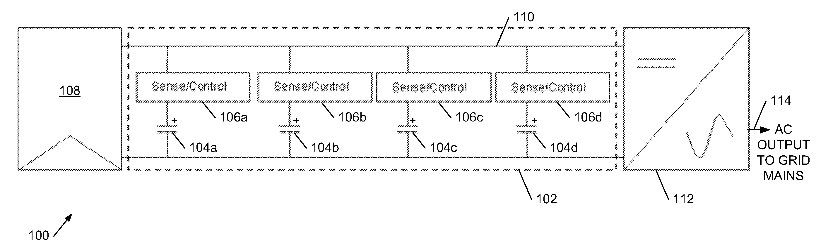
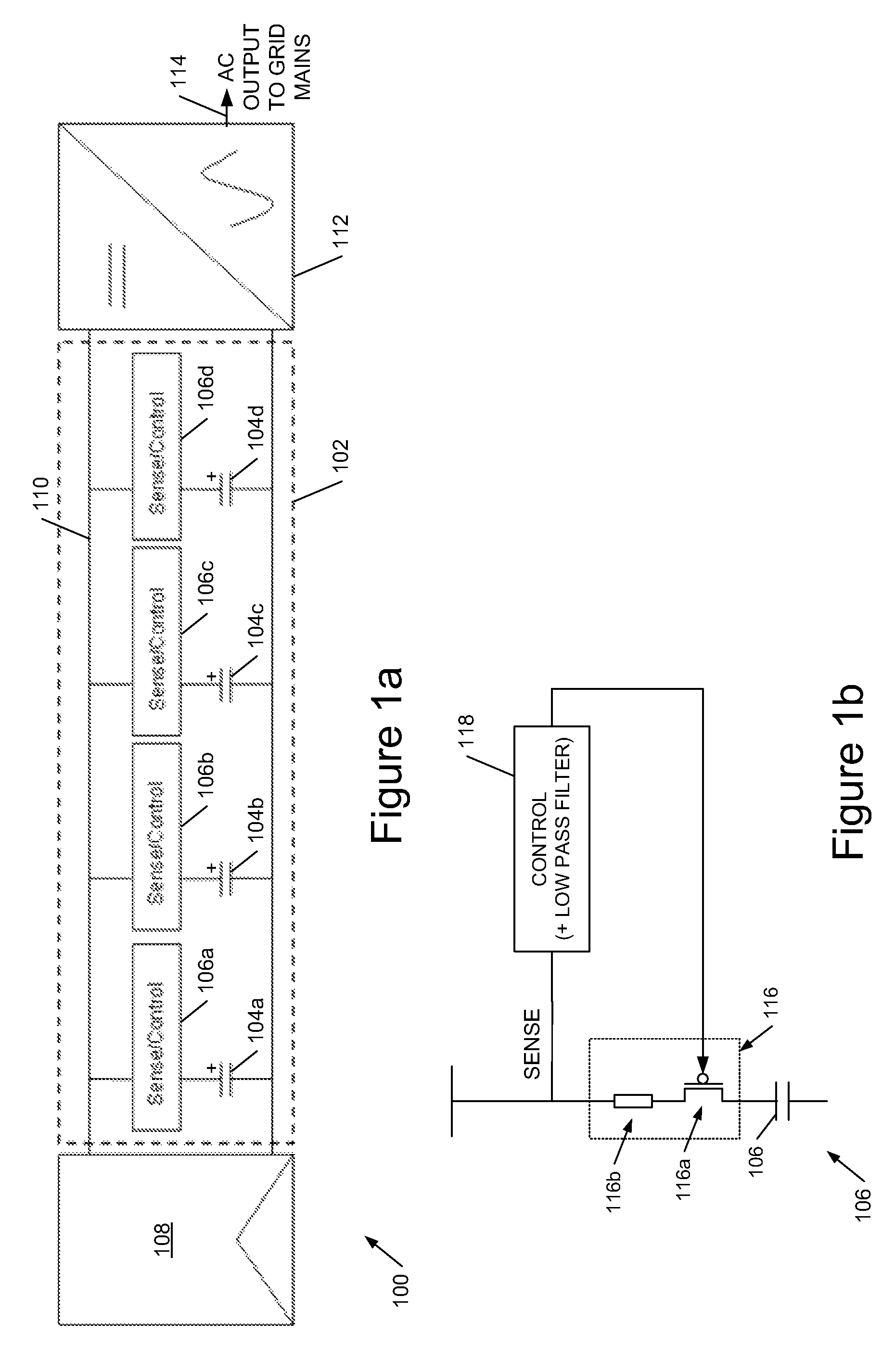
[0028]Referring to FIG. 1, this shows an embodiment of a photovoltaic power conditioning unit 100 comprising a bank 102 of parallel-connected electrolytic capacitors 104a-d each with a respective sense / control circuit 106a-d. The power conditioning unit receives input from one or more photovoltaic panels 108 which provide dc power to a dc link 110 of the inverter, which in turn provides power to a dc-to-ac converter 112 which provides an ac output 114 to the grid mains.

[0029]An example embodiment of the sense control circuit 106 is shown in FIG. 1b, in the example comprising a senseFET 116 comprising a MOSFET 116a and a current-sensing resistance 116b. A voltage on the current-sensing resistance is sensed by a control circuit 118, which in preferred embodiments incorporates a low-pass filter to attenuate a current-sense signal at the switching frequency of dc-to-ac converter 112. The control circuit 118 is configured to switch FET 116 off when the sensed-current exceeds a threshold ...


PUM


Abstract

We describe a photovoltaic power conditioning unit for delivering power from multiple photovoltaic panels to an ac mains power supply output, comprising: a dc input for receiving power from multiple photovoltaic panels; an ac output for delivering ac power to the ac supply; a bank of electrolytic energy storage capacitors for storing energy from the dc source for delivery to the ac supply; a dc-to-ac converter coupled to the ac output and having an input coupled to the bank for converting energy stored in the bank to ac power for the ac supply; and further comprising: a plurality of sense and control circuits, one for each capacitor in the bank, wherein each circuit is coupled in series with a capacitor, and is configured to disconnect the associated capacitor from the bank upon detection of a current flow thorough the associated capacitor of greater than a threshold current value.

Description

CLAIM OF BENEFIT TO PRIOR APPLICATIONS[0001]This application claims benefit of an earlier-filed United Kingdom Patent Application 1100796.0, filed Jan. 18, 2011, which is incorporated herein by reference.FIELD OF THE INVENTION[0002]This invention relates to power conditioning units for delivering power from a dc power source, in particular one or more photovoltaic panels, to an ac output, either for connecting directly to the mains (grid) utility supply or for powering mains (grid) devices, independently from the mains utility supply. More particularly the invention relates to techniques for increasing the reliability of such devices.BACKGROUND TO THE INVENTION[0003]We have previously described techniques for energy control in power conditioning units (inverters) which enable the construction of a dc-to-mains power converter which does not need to use electrolytic capacitors (see U.S. Pat. No. 8,089,785 and GB2,434,490A). We now describe alternative techniques for increasing the rel...

Claims


Application Information

Patent Timeline
Patent Type & Authority Patents(United States)
IPC IPC(8): H02J3/00H02J1/00
CPCH01L31/02021H02H7/16H02M7/48H02J3/383Y02E10/563H02J3/00Y10T307/729Y10T307/724H02J2300/24H02J3/381Y02E10/56H02J3/46H02H7/12H02M7/44
Inventor MUMTAZ, ASIM
Owner TESLA INC
Why Eureka
Try Eureka