SQUID-system having increased flux voltage transfer function

a technology of flux voltage and flux voltage, which is applied in the direction of magnetic measurement, magnetic field measurement using superconductive devices, instruments, etc., can solve the problems of noise limitation of the system, inability to use in many applications, and lack of matching the impedance of the squid to the amplifier input, so as to simplify the required reading of electronics and increase the measuring sensitivity of the system

Active Publication Date: 2014-03-25
INST FUER PHOTONISCHE TECHNOLOGIEN EV
View PDF3 Cites 4 Cited by
  • Summary
  • Abstract
  • Description
  • Claims
  • Application Information

AI Technical Summary

Benefits of technology

[0012]The object of the present invention is to provide a circuit arrangement which supplies an increased FLUX-VOLTAGE-TRANSFER-function of a dc SQUID which considerably increases the measuring sensitivity of the system and simplifies the required reading electronics.

Problems solved by technology

In such an electronics system the band width and the signal sequence rate (slew rate) are limited by the modulation frequency so that it cannot be used in many applications.
But the essential disadvantage of this electronics is the lack of matching the impedances of the SQUID to the amplifier input.
Hence the intrinsic noise of the electronics as well as of the drift plays an important role in the noise limited resolution of the system.
These problems occur above all at low frequencies, so that the application is restricted in some cases.
One disadvantage of the respective two-stage-system is also made visible in FIG. 3b.
The resulting flux-voltage curve is very complicated due to the periodicities of the SQUID and in the SQUID-array and leads to a number of stable operation points of the FLL having respective different transfer functions and noise characteristics.
However, the disadvantage of this approach remains the same.

Method used


Image

  • SQUID-system having increased flux voltage transfer function
  • SQUID-system having increased flux voltage transfer function
  • SQUID-system having increased flux voltage transfer function

Examples


Embodiment Construction

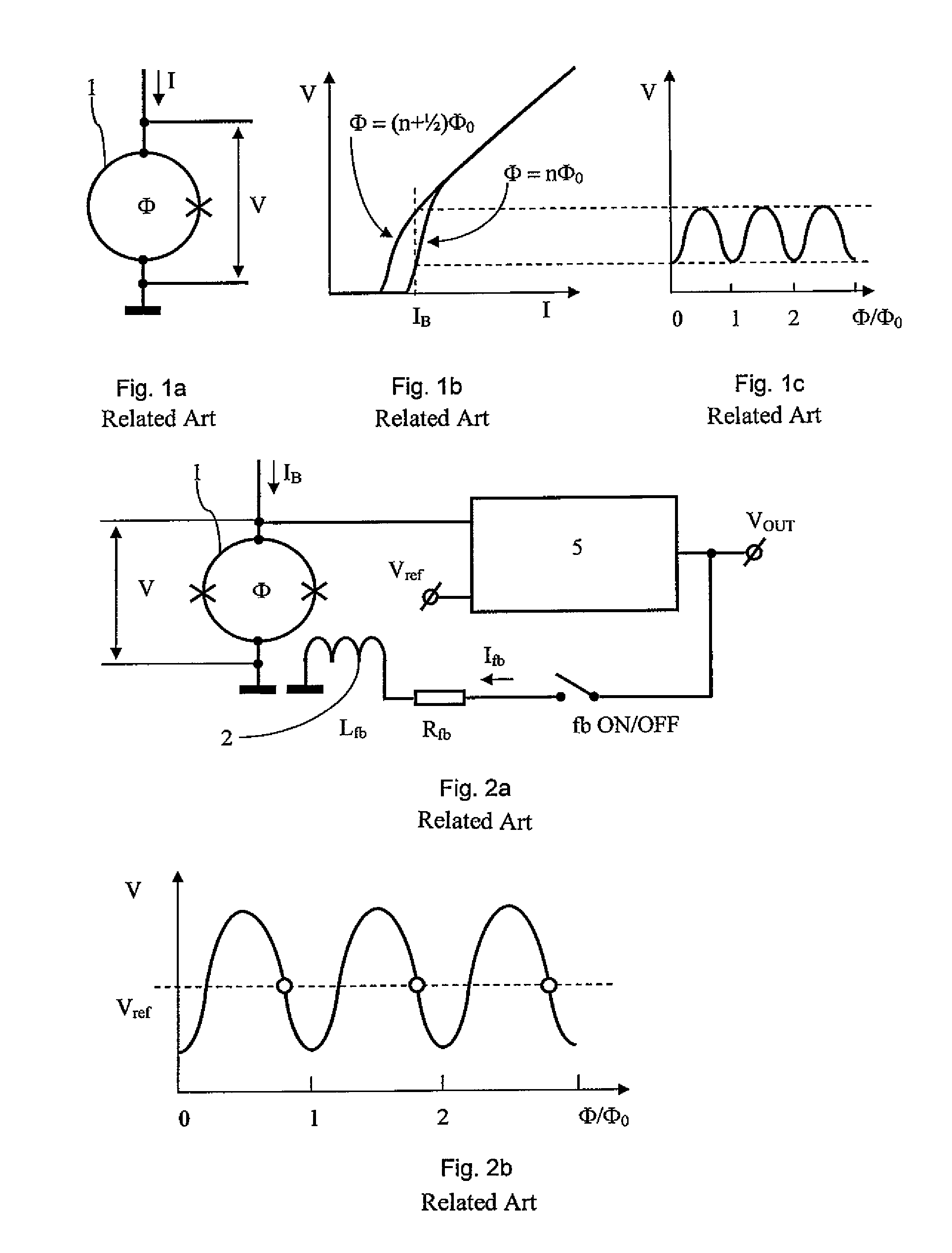
[0031]To begin with and for better understanding of the invention, the heretofore common way in the prior art for amplifying the signals of a dc SQUID will be outlined by reference to the FIGS. 1 to 4:

[0032]To this end FIG. 1a shows a single dc SQUID 1 and FIG. 1b a current-voltage characteristic (I-V-characteristic) of the dc SQUID at the two extreme values of the flux (Φ) in the SQUID, wherein Φ0 stands for a flux quantum. FIG. 1c shows the respective flux-voltage characteristic (Φ-V-characteristic) of the SQUID when it is provided with an operational current feed IB.

[0033]FIG. 2a shows a dc SQUID 1 having the usual feedback electronics. When the switch fb ON / OFF is shut (“ON” position) the electronics 5 produces a current Ifb which is proportional to the voltage difference V−Vref across the resistor Rfb and the feedback coil Lfb. FIG. 2b shows the corresponding SQUID voltage as a function of the flux in the SQUID. The feedback coupling circuit keeps the entire flux constant in th...


PUM


Abstract

The invention relates to a SQUID system having an increased flux voltage transfer function. The object of disclosing a circuit configuration providing an increased flux voltage transfer function of a SQUID, wherein the measurement sensitivity of the system is noticeably increased and the required readout electronics are simplified, is achieved in that at least one SQIF is provided as an amplifier circuit and is connected downstream of the first SQUID, wherein a coupling coil electrically connected to the first SQUID is directly associated with all loops of the SQIF.

Description

BACKGROUND OF THE INVENTION[0001]The invention relates to a SQUID system having an increased flux voltage transfer function.[0002]The present invention refers to a superconducting quantum interference device, dc SQUID adapted for the very sensitive measurement of the magnetic flux and other physical quantities which may be converted into a magnetic flux (such as, for example, magnetic fields, magnetic field gradients, electrical current, and so forth).[0003]The superconducting quantum interference devices, dc SQUIDs are at present the most sensitive detectors for determining a magnetic flux. Their function is based upon two physical phenomena, namely upon the quantizing of the magnetic flux within a superconducting loop and upon the Josephson Effect of two weakly coupled superconductors. A SQUID is a superconducting loop interrupted by at least one Josephson contact. There are known two basic kinds of SQUIDs [refer to A. Barone, G. Paterno: “Physics and Application of the Josephson ...

Claims


Application Information

Patent Timeline
Patent Type & Authority Patents(United States)
IPC IPC(8): G01R33/02
CPCG01R33/035
Inventor ZAKOSARENKO, VYACHESLAVSTOLZ, RONNYMEYER, HANS-GEORG
Owner INST FUER PHOTONISCHE TECHNOLOGIEN EV
Why Eureka
Try Eureka