Arrival angle estimation system, communication device, and communication system

a technology of estimation system and angle, applied in direction finders using radio waves, transmission monitoring, instruments, etc., can solve problems such as difficult incorporation into compact apparatuses, system use, communication errors, etc., and achieve the effect of sufficient level of accuracy and sufficient estimation accuracy

Inactive Publication Date: 2014-03-25
SONY CORP
View PDF28 Cites 6 Cited by
  • Summary
  • Abstract
  • Description
  • Claims
  • Application Information

AI Technical Summary

Benefits of technology

[0016]It is also desirable to provide a superior arrival angle estimation system, communication device, and communication system which are used within a relatively short distance and under conditions in which a sufficient line of sight can be provided, and are configured to be simple, compact, and low cost.
[0051]The present invention assumes that the wireless communication apparatus uses a technique based on IEEE802.11, and arrival angle estimation can be performed in a satisfactory manner in both of the networking modes of the ad-hoc mode and the infrastructure mode. Further, a sufficient estimation accuracy on the order of ±30 degrees can be accomplished by a combination of an existing radio technology such as IEEE802.11 and simple directional antennas.

Problems solved by technology

In many wireless communications, data is transmitted under a multi-path environment in which an overlap of a direct wave and a plurality of reflected waves / delay waves arrives at the receiving device, so delay distortion due to multi-path reception may occur, causing an error in communication.
As such, these techniques require an antenna with a special mechanism, such as an array antenna with high dimensionality and large size, and systems using these techniques are expensive due to the complex computations involved, making their incorporation into compact apparatuses difficult.
However, it is difficult to incorporate a rotary mechanism that rotationally drives antennas into a compact mobile apparatus, and the presence of such a movable part causes problems in terms of fault tolerance and maintenance.

Method used


Image

  • Arrival angle estimation system, communication device, and communication system
  • Arrival angle estimation system, communication device, and communication system
  • Arrival angle estimation system, communication device, and communication system

Examples


Embodiment Construction

[0078]An embodiment of the present invention will be described in detail with reference to the drawings.

A. Configuration Of Antenna

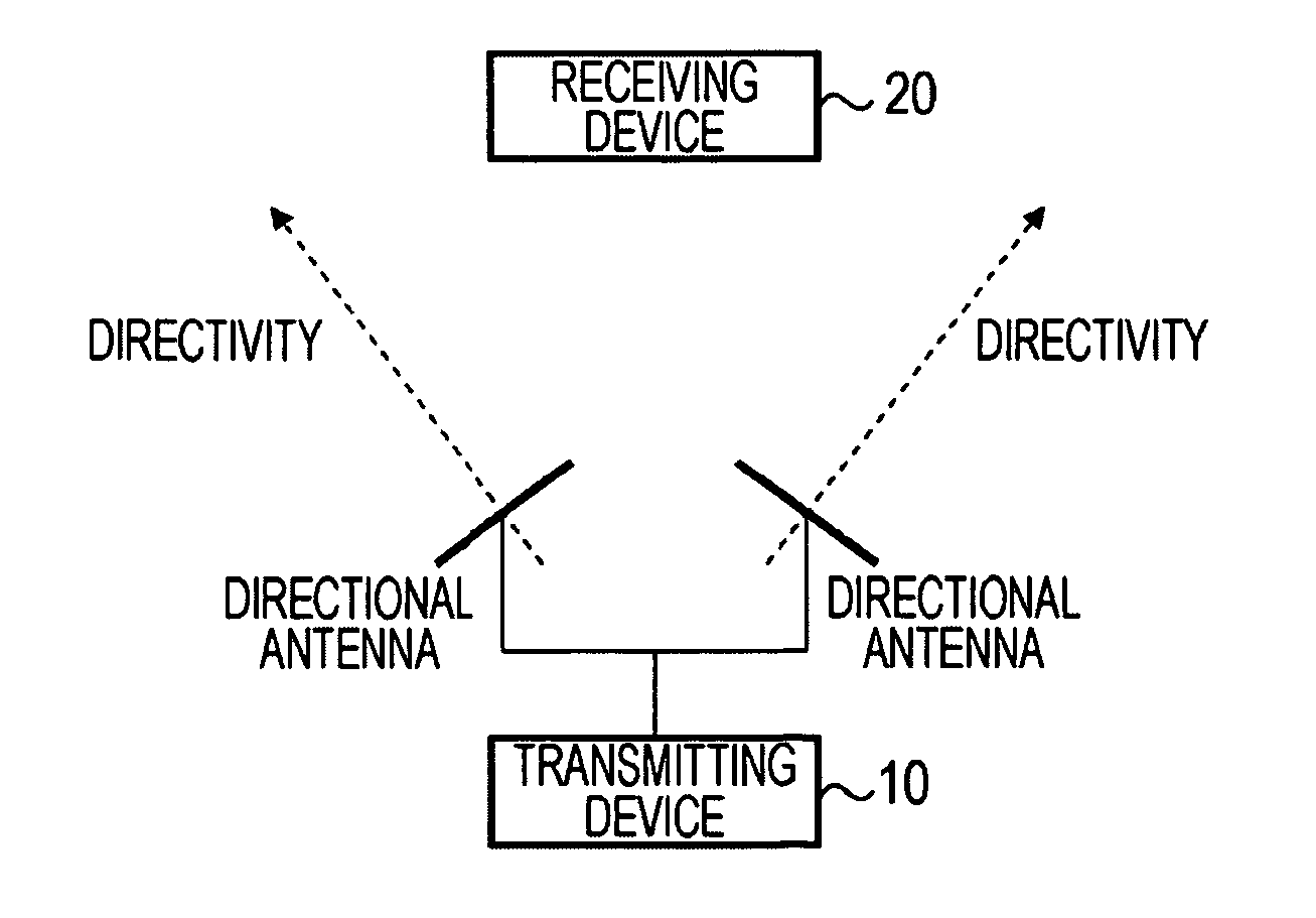
[0079]An arrival angle estimation system according to an embodiment of the present invention assumes use of a wireless communication device equipped with a plurality of antennas as a precondition. At present, most of wireless communication devices are equipped with a plurality of antennas for diversity operation, so most of wireless communication devices that are commonly available satisfy this precondition.

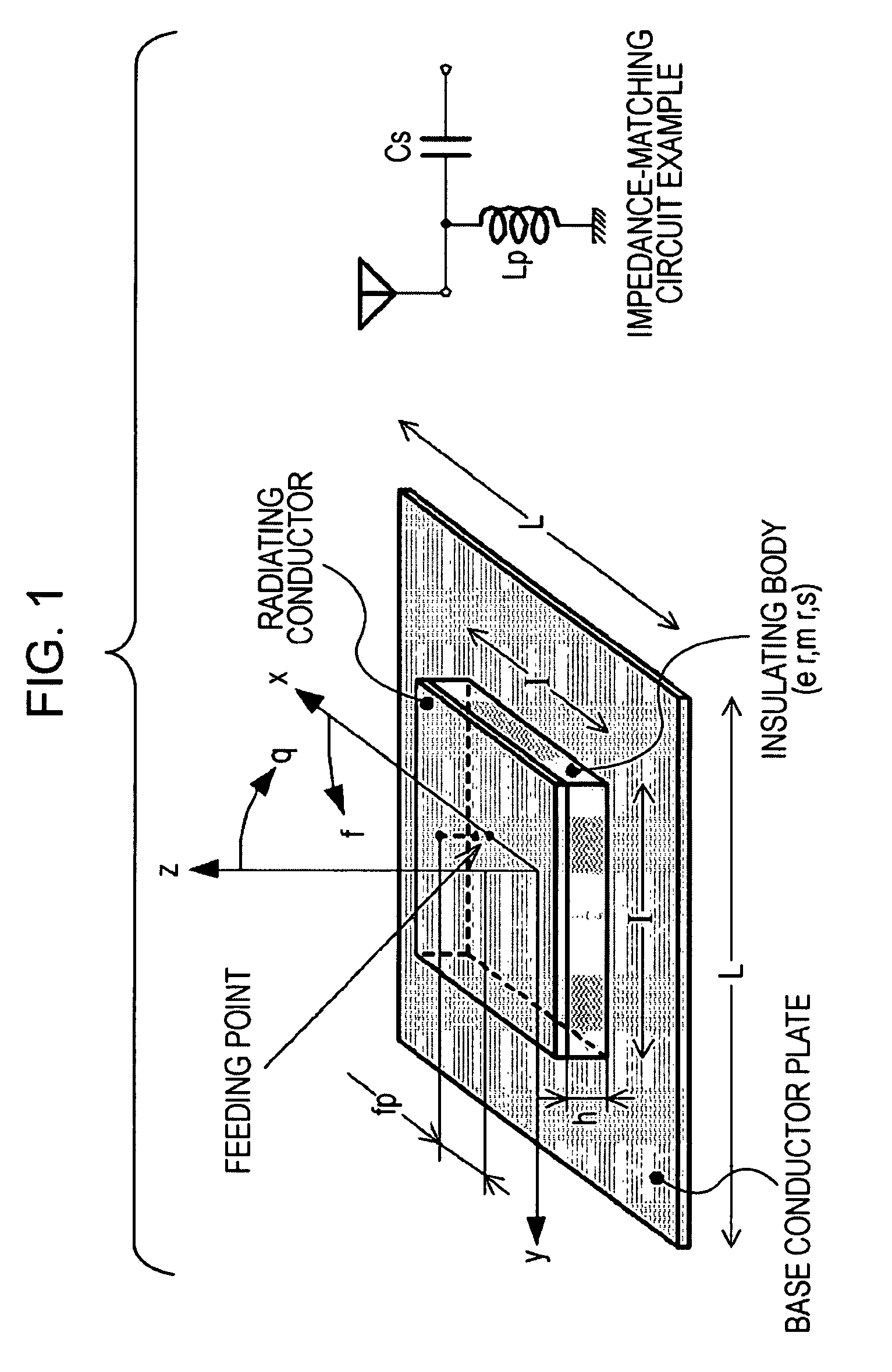
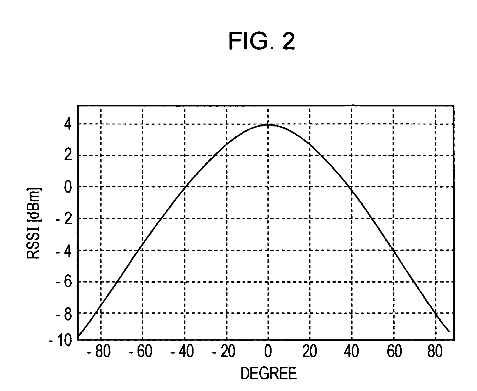
[0080]Mainly assumed as an application of the arrival angle estimation system according to an embodiment of the present invention is its application to compact apparatuses such as mobile telephones, so generally an accuracy of 30 to 40 degrees suffices. Therefore, it is suitable to use a compact directional antenna with a half-power angle of about 40 to 120 degrees. For example, an inexpensive and compact microstrip antenna whose length of one side is...


PUM


Abstract

An arrival angle estimation system includes a transmitting device and a receiving device and estimates an arrival angle at which frames transmitted by radio from the transmitting device arrive at the receiving device. The transmitting device includes two directional antennas each arranged so that its directivity is tilted at ±θ degrees with respect to the front of the transmitting device. The receiving device includes a directional antenna having directivity toward the front of the receiving device. Frames are transmitted alternately from the respective directional antennas of the transmitting device, and received signal strengths of the frames on the receiving device side for the respective transmitting directional antennas are compared with each other to estimate the arrival angle.

Description

CROSS REFERENCES TO RELATED APPLICATIONS[0001]The present invention contains subject matter related to Japanese Patent Application JP 2007-141820 filed in the Japanese Patent Office on May 29, 2007, the entire contents of which are incorporated herein by reference.BACKGROUND OF THE INVENTION[0002]1. Field of the Invention[0003]The present invention relates to an arrival angle estimation system for estimating the angle of arrival of radio waves, a communication device, and a communication system, and particularly to an arrival angle estimation system, a communication device, and a communication system which are used in a wireless communication device incorporating a wireless LAN such as IEEE802.11.[0004]More specifically, the present invention relates to an arrival angle estimation system, a communication device, and a communication system which are used within a short distance range under the condition of sufficient line of sight and are simple, compact, and low cost, in particular,...

Claims


Application Information

Patent Timeline
Patent Type & Authority Patents(United States)
IPC IPC(8): G01S3/72G01S1/08G01S3/16H04B17/00H04W16/28H04W84/10H04W88/02
CPCH04B7/0822G01S1/14G01S1/10G01S3/18H04W88/02G01S3/16H01Q3/06H01Q3/00
Inventor NISHIDA, YOSHIFUMI
Owner SONY CORP
Why Eureka
Try Eureka