Remotely reconfigurable distributed antenna system and methods

a distributed antenna and remote reconfiguration technology, applied in the field of wireless communication systems, can solve the problems of wasting many base stations' capacity, presenting unexpected challenges with regard to available wireless capacity and data throughput, and the most difficult challenges faced by network operators, and achieves the effects of enhancing the efficiency and traffic capacity of the operators' wireless networks, facilitating the use of radio resource efficiency, and facilitating the utilization of radio resource efficiency

Active Publication Date: 2014-03-25
DALI WIRELESS
View PDF31 Cites 91 Cited by
  • Summary
  • Abstract
  • Description
  • Claims
  • Application Information

AI Technical Summary

Benefits of technology

[0016]The present invention substantially overcomes the limitations of the prior art discussed above. The advanced system architecture of the present invention provides a high degree of flexibility to manage, control, enhance and facilitate radio resource efficiency, usage and overall performance of the distributed wireless network. This advanced system architecture enables specialized applications and enhancements including flexible simulcast, automatic traffic load-balancing, network and radio resource optimization, network calibration, autonomous / assisted commissioning, carrier pooling, automatic frequency selection, radio frequency carrier placement, traffic monitoring, traffic tagging, and indoor location determination using pilot beacons. The present invention can also serve multiple operators, multi-mode radios (modulation-independent) and multi-frequency bands per operator to increase the efficiency and traffic capacity of the operators' wireless networks.
[0017]Accordingly, it is an object of the present invention to provide a capability for Flexible Simulcast. With Flexible Simulcast, the amount of radio resources (such as RF carriers, CDMA codes or TDMA time slots) assigned to a particular RRU or group of RRUs by each RRU Access Module can be set via software control as described hereinafter to meet desired capacity and throughput objectives or wireless subscriber needs. To achieve these and other objects, an aspect of the present invention employs software-programmable frequency selective Digital Up-Converters (DUCs) and Digital Down-Converters (DDCs). A software-defined Remote Radio Head architecture is used for cost-effective optimization of the radio performance. Frequency selective DDCs and DUCs at the Remote Radio Head enable a high signal to noise ratio (SNR) which maximize the throughput data rate. An embodiment shown in FIG. 1 depicts a basic structure and provides an example of a Flexible Simulcast downlink transport scenario. FIG. 2 depicts an embodiment of a basic structure of a Flexible Simulcast uplink transport scenario.
[0018]It is a further object of the present invention to facilitate conversion and transport of several discrete relatively narrow RF bandwidths. In another aspect of the invention, an embodiment converts only that plurality of specific, relatively narrow bandwidths that carry useful information. Thus, this aspect of the present invention allows more efficient use of the available optical fiber transport bandwidth for neutral host applications, and facilitates transport of more operators' band segments over the optical fiber. To achieve the above result, the present invention utilizes frequency-selective filtering at the Remote Radio Head which enhances the system performance. In some embodiments of this aspect of the invention, noise reduction via frequency-selective filtering at the Remote Radio Head is utilized for maximizing the SNR and consequently maximizing the data throughput. It is a further object of the present invention to provide CDMA and WCDMA indoor location accuracy enhancement. In an aspect of the present invention, an embodiment provides enhanced location accuracy performance by employing pilot beacons. FIG. 3 depicts a typical indoor system employing multiple Remote Radio Head Units (RRUs) and a central Digital Access Unit (DAU). The Remote Radio Heads have a unique beacon that is distinct and identifies that particular indoor cell. The mobile user will use the beacon information to assist in the localization to a particular cell.
[0019]It is a further object of the present invention to enhance GSM and LTE indoor location accuracy. In another aspect, an embodiment of the present invention provides localization of a user based on the radio signature of the mobile device. FIG. 4 depicts a typical indoor system employing multiple Remote Radio Head Units (RRUs) and a central Digital Access Unit (DAU). In accordance with the invention, each Remote Radio Head provides unique header information on data received by that Remote Radio Head. The system of the invention uses this header information in conjunction with the mobile user's radio signature to localize the user to a particular cell.

Problems solved by technology

Wireless and mobile network operators face the continuing challenge of building networks that effectively manage high data-traffic growth rates.
One of the most difficult challenges faced by network operators is caused by the physical movement of subscribers from one location to another, and particularly when wireless subscribers congregate in large numbers at one location.
If the indoor wireless network resources were properly sized during the design process for subscriber loading as it is during normal working hours when subscribers are in their normal work areas, it is very likely that the lunchtime scenario will present some unexpected challenges with regard to available wireless capacity and data throughput.
Although this approach typically yields a high quality of service, the notable disadvantage of this approach is that during a major part of the time many of the base stations' capacity is being wasted.
Since a typical indoor wireless network deployment involves capital and operational costs which are assessed on a per-subscriber basis for each base station, the typically high total life cycle cost for a given enterprise facility is far from optimal.
A notable disadvantage of this approach is that most enterprises seem to undergo frequent re-arrangements and re-organizations of various groups within the enterprise.
Therefore, it's highly likely that the initial setup will need to be changed from time to time, requiring deployment of additional staff and contract resources with appropriate levels of expertise regarding wireless networks.
Another issue is that it's not always correct or best to make the same DAS remote unit configuration changes back and forth on each day of the week at the same times of day.
Frequently it is difficult or impractical for an enterprise IT manager to monitor the subscriber loading on each base station.
And it is almost certain that the enterprise IT manager has no practical way to determine the loading at a given time of day for each DAS remote unit; they can only guess.
Another major limitation of prior art DAS deployments is related to their installation, commissioning and optimization process.
The process of performing such deployment optimization is frequently characterized as trial-and-error and as such, the results may not be consistent with a high quality of service.
A major limitation of prior art DAS equipment employing digital transmission links such as optical fiber or wired Ethernet is the fact that the prior-art RF-to-digital conversion techniques utilize an approach whereby the system converts a single broad RF bandwidth of e.g., 10 to 25 MHz to digital.
This approach frequently leads to inefficiencies within the DAS which limit the DAS network capacity.
It has been demonstrated that GPS signals from satellites outdoors don't propagate well into the indoor space.
A notable disadvantage of this approach for an indoor DAS application is that since the CDMA Pilot Beacon unit is a separate and dedicated device and not integrated within the DAS, it would likely be costly to deploy.
No known solution for indoor location accuracy enhancement has been publicly proposed for WCDMA networks.
A notable disadvantage of this approach for an indoor DAS application is that, since the LMU is a separate and dedicated device and not integrated within the DAS, it is costly to deploy.
The LMU backhaul cost adds to the total cost of deploying the enhanced accuracy E-911 solution for GSM networks.
Despite the availability of the already technically-proven LMU approach, it has not been widely deployed in conjunction with indoor DAS.

Method used


Image

  • Remotely reconfigurable distributed antenna system and methods
  • Remotely reconfigurable distributed antenna system and methods
  • Remotely reconfigurable distributed antenna system and methods

Examples


Embodiment Construction

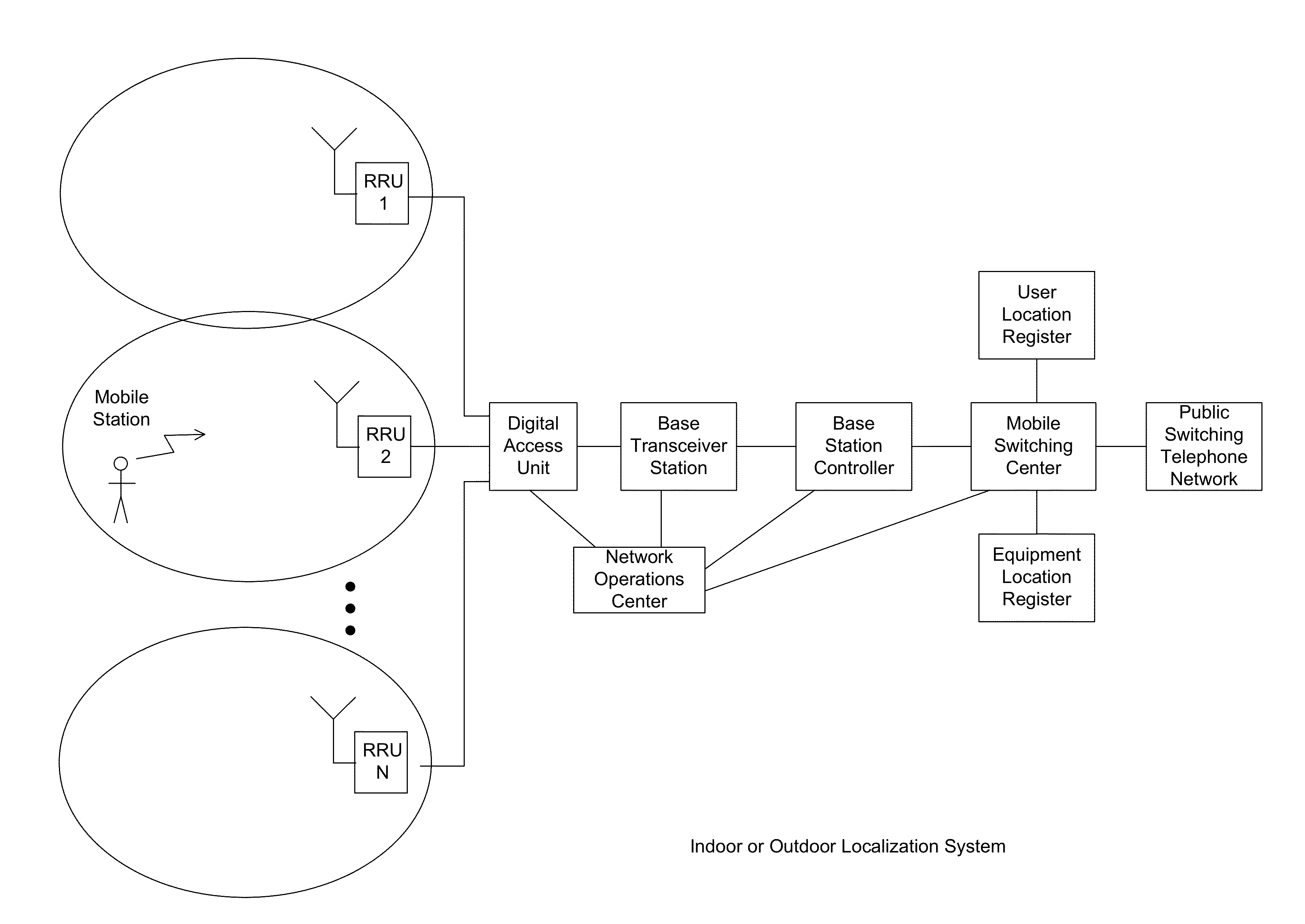
[0031]The present invention is a novel Reconfigurable Distributed Antenna System that provides a high degree of flexibility to manage, control, re-configure, enhance and facilitate the radio resource efficiency, usage and overall performance of the distributed wireless network. An embodiment of the Reconfigurable Distributed Antenna System in accordance with the present invention is shown in FIG. 1. The Flexible Simulcast System 100 can be used to explain the operation of Flexible Simulcast with regard to downlink signals. The system employs a Digital Access Unit functionality (hereinafter “DAU”). The DAU serves as an interface to the base station (BTS). The DAU is (at one end) connected to the BTS, and on the other side connected to multiple RRUs. For the downlink (DL) path, RF signals received from the BTS are separately down-converted, digitized, and converted to baseband (using a Digital Down-Converter). Data streams are then I / Q mapped and framed. Specific parallel data streams...


PUM


Abstract

The present disclosure is a novel utility of a software defined radio (SDR) based Distributed Antenna System (DAS) that is field reconfigurable and support multi-modulation schemes (modulation-independent), multi-carriers, multi-frequency bands and multi-channels. The present disclosure enables a high degree of flexibility to manage, control, enhance, facilitate the usage and performance of a distributed wireless network such as flexible simulcast, automatic traffic load-balancing, network and radio resource optimization, network calibration, autonomous / assisted commissioning, carrier pooling, automatic frequency selection, frequency carrier placement, traffic monitoring, traffic tagging, pilot beacon, etc. As a result, the SDR DAS can increase the efficiency and traffic capacity of the operators' wireless network.

Description

RELATED APPLICATIONS[0001]This application claims the benefit of U.S. Patent Application Ser. No. 61 / 382,836, filed on Sep. 14, 2010, entitled REMOTELY RECONFIGURABLE DISTRIBUTED ANTENNA SYSTEM AND METHODS, which is hereby incorporated by reference for all purposes.FIELD OF THE INVENTION[0002]The present invention generally relates to wireless communication systems employing Distributed Antenna Systems (DAS) as part of a distributed wireless network. More specifically, the present invention relates to a DAS utilizing software defined radio (SDR).BACKGROUND OF THE INVENTION[0003]Wireless and mobile network operators face the continuing challenge of building networks that effectively manage high data-traffic growth rates. Mobility and an increased level of multimedia content for end users requires end-to-end network adaptations that support both new services and the increased demand for broadband and flat-rate Internet access. One of the most difficult challenges faced by network oper...

Claims


Application Information

Patent Timeline
Patent Type & Authority Patents(United States)
IPC IPC(8): H04W72/00H04L45/60
CPCH03F2201/3233H04W24/02H03F2200/204H04L25/02H03F3/24H04L5/0048H03F2201/3224H03F1/3247H04L12/6418H04L67/1001H04Q2213/1301H04W88/085H04B10/25753H04B10/25759H04L25/0264H04W72/52H04B10/2575H04L5/0032H04Q11/0067H04Q2011/0081H04W72/0453H04L45/56H04L47/125H04W40/02
Inventor LEMSON, PAULSTAPLETON, SHAWN PATRICKTRAJKOVIC, SASALEE, ALBERT S.
Owner DALI WIRELESS
Why Eureka
Try Eureka