Control device of lock-up clutch

a control device and lock-up clutch technology, which is applied in the direction of machine control, instruments, process control, etc., can solve the problems of increasing noise or vibration, unable to obtain sufficient lock-up clutch capacity against engine torque, and high temperature of the surface of the friction member (facing member), so as to effectively suppress the rise in the internal temperature and the rise in the facing temperature

Active Publication Date: 2014-03-25
HONDA MOTOR CO LTD
View PDF13 Cites 5 Cited by
  • Summary
  • Abstract
  • Description
  • Claims
  • Application Information

AI Technical Summary

Benefits of technology

[0009]The present invention is made in view of the above points, and it is an object of the present invention to provide a control device of a lock-up clutch capable of effectively suppressing rise in facing temperature and rise in internal temperature of a torque converter while continuing slip control in the case where the facing temperature is raised by means of the slip control for the lock-up clutch.
[0016]According to the control device of the lock-up clutch of the present invention, in the case where the estimate value of the facing temperature continues to exceed the first threshold temperature for more than the predetermined time when the slip control for the lock-up clutch is carried out, switching of the target slip ratio map is carried out from the normal slip ratio map to the modified slip ratio map. Thus, it is possible to effectively suppress rise in facing temperature and rise in internal temperature of the torque converter while continuing slip control for the lock-up clutch. Therefore, it is possible to achieve endurance enhancement of the lock-up clutch and component parts of the torque converter, improvement of fuel economy and effective suppression of vibration and noise. Further, since switching of the target slip ratio map is carried out on the basis of the estimate value of the facing temperature, it is possible to carry out switching of the target slip ratio map at appropriate timing.
[0019]According to these configurations, after determining whether the facing calorific value is in the decreasing tendency or increasing tendency against a change in the slip ratio on the basis of the current target slip ratio, it is possible to select one modified slip ratio map, by which it is expected that the facing calorific value is lowered. Therefore, it is possible to lower the facing temperature of the lock-up clutch quickly and surely.
[0021]According to this configuration, in the case where the estimate value of the facing temperature is lowered to become an acceptable range by means of switching of the slip ratio map to the modified slip ratio map, the slip ratio of the lock-up clutch is returned to the normal slip ratio. Thus, it is possible to further improve fuel economy and to effectively suppress vibration and noise. In particular, by preparing the target slip ratio map capable of optimizing driving force and fuel economy of the vehicle as the normal slip ratio map, it is possible to effectively achieve both optimization of the driving force and fuel economy of the vehicle by the normal slip ratio map and suppression of rise in the facing temperature by the modified slip ratio map.
[0023]According to the control device of the lock-up clutch of the present invention, it is possible to effectively suppress rise in facing temperature and rise in internal temperature of a torque converter while continuing slip control in the case where the facing temperature is raised due to the slip control for the lock-up clutch.

Problems solved by technology

On the other hand, since variation in engine torque is directly transmitted to a drive system by means of engagement of the lock-up clutch, this causes an increase in noise or vibration.
However, in the case where the lock-up clutch is continuously slipped, a surface of a friction member (facing member) becomes high temperature.
Thus, there is a fear that a sufficient lock-up clutch capacity against the engine torque cannot be obtained.
Further, when the surface of the friction member becomes high temperature, heat generation due to a work loss is increased by enlarging a slippage amount of the torque converter in addition to heat generation of the friction member.
This causes hydraulic oil in the torque converter to become high temperature, thereby leading to acceleration of deterioration of a resin component or a rubber component.
Further, when the rise in temperature in the torque converter becomes marked, there is a possibility that any hydraulic oil path in the torque converter is damaged in the worst-case scenario.
However, there has been a problem as follows.
In the case where the lock-up clutch completely engages, vibration and noise in driving force transmission is deteriorated.
On the other hand, in the case where engagement of the lock-up clutch is completely released, fuel economy is deteriorated.
Thus, in the case where the slippage amount of the lock-up clutch is controlled on the basis of the internal temperature estimated from the work loss of the torque converter, there is a fear that delay in timing to reduce the slippage amount occurs.
Therefore, there has been a problem that the facing temperature cannot be controlled to become assumed temperature with high accuracy.

Method used


Image

  • Control device of lock-up clutch
  • Control device of lock-up clutch
  • Control device of lock-up clutch

Examples


Embodiment Construction

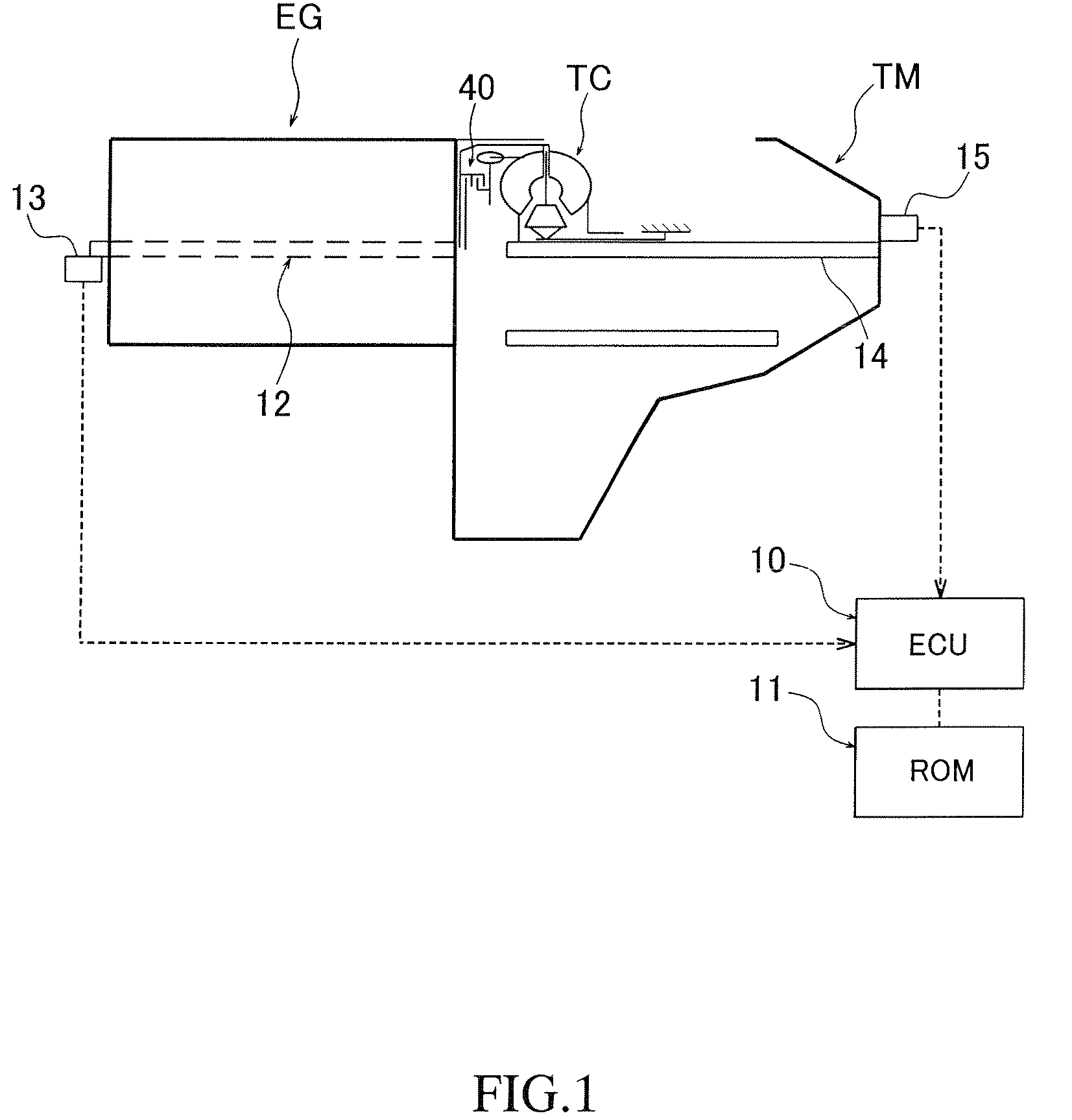
[0031]Hereinafter, an embodiment of the present invention will be described in detail with reference to the appending drawings. FIG. 1 is a view showing a schematic configuration of a drive system mounted on a vehicle. A drive system shown in FIG. 1 is configured so as to include an engine EG, an automatic transmission TM and a torque converter TC for connecting the engine EG to the automatic transmission TM. A lock-up clutch 40 is provided in the torque converter TC. Further, an electronic control unit (hereinafter, referred to as an “ECU”) 10 for carrying out control for the automatic transmission TM including the torque converter TC and a ROM (storage section) 11 for storing data required for control by the ECU 10 are provided. Further, a crank shaft revolution indicator 13 for detecting the number of revolutions of a crank shaft 12 and a main shaft revolution indicator 15 for detecting the number of revolutions of a main shaft 14 are installed.

[0032]The ECU 10 is adapted to inpu...


PUM


Abstract

A control device for controlling an engagement state of a lock-up clutch is provided. A plurality of target slip ratio maps include a normal slip ratio map having a characteristic line of a target slip ratio defined in accordance with an engine load at a normal vehicle running condition and a modified slip ratio map having a characteristic line of the target slip ratio to become a facing calorific value lower than a facing calorific value corresponding to the slip ratio retrieved from the normal slip ratio map. In the case where an estimate value of the facing temperature continues to exceed first threshold temperature for more than predetermined time when to carry out slip control using the normal slip ratio map, control to switch the target slip ratio map from the normal slip ratio map to the modified slip ratio map is carried out.

Description

CROSS-REFERENCE TO RELATED APPLICATION[0001]The present disclosure relates to subject matter contained in Japanese Patent Application No. 2009-138040, filed on Jun. 9, 2009, the disclosure of which is expressly incorporated herein by reference in its entirety.BACKGROUND OF THE INVENTION[0002]1. Field of the Invention[0003]The present invention relates to a control device of a lock-up clutch for controlling an engagement state of the lock-up clutch with which a torque converter is provided, and particularly, the present invention relates to a control device capable of controlling rise in facing temperature due to slip control for the lock-up clutch.[0004]2. Description of the Related Art[0005]In an automatic transmission mounted on a vehicle, a torque converter for amplifying torque has been utilized. A lock-up clutch for directly connecting an impeller to a turbine is provided in most of the torque converters. By providing the lock-up clutch to the torque converter, power transmissi...

Claims


Application Information

Patent Timeline
Patent Type & Authority Patents(United States)
IPC IPC(8): F16H61/14G06F17/00
CPCF16H2061/145F16H2061/1224F16H2059/725F16H2057/016F16H61/143Y10T477/735Y10T477/755Y10T477/26Y10T477/50Y10T477/73
Inventor TAKAMATSU, MASAAKIISHIKAWA, YUTAKAABE, SHINYA
Owner HONDA MOTOR CO LTD
Why Eureka
Try Eureka