
System and method for harvesting electrical energy by linear induction

a linear induction and electrical energy technology, applied in the field of small arms weapon systems, can solve the problems of insufficient use of rechargeable batteries, inability to meet the needs of fielded and fighting soldiers,

Inactive Publication Date: 2014-04-01
UNITED STATES OF AMERICA THE AS REPRESENTED BY THE SEC OF THE ARMY
View PDF6 Cites 19 Cited by
  • Summary
  • Abstract
  • Description
  • Claims
  • Application Information

AI Technical Summary

Benefits of technology

The present invention is a new type of generator that uses linear induction to harness energy from a weapon system. This invention solves the problem of modern war-fighters not having access to portable electric power on the battlefield. The generator is self-powering or charging, which means it can provide energy for electronic devices. This invention is designed to make life easier for war-fighters and improve their overall efficiency.

Problems solved by technology

While these technological advances provide the armed forces with an important advantage in battle, they also present inherent logistics problems.
More specifically, the batteries that support the electronic devices have a finite life.
Even rechargeable battery technology is of limited use to a fielded and fighting soldier.
Shortage of fresh batteries and the possibility of depletion while in combat pose a serious threat to the modern soldier trying to exploit the enhanced fighting capabilities technology.
However, there are numerous challenges associated with practically capturing electrical energy from the rounds that are shot from a weapon, because significant energy is wasted in mechanical motion and heat.

Method used


Image

  • System and method for harvesting electrical energy by linear induction
  • System and method for harvesting electrical energy by linear induction
  • System and method for harvesting electrical energy by linear induction

Examples


Embodiment Construction

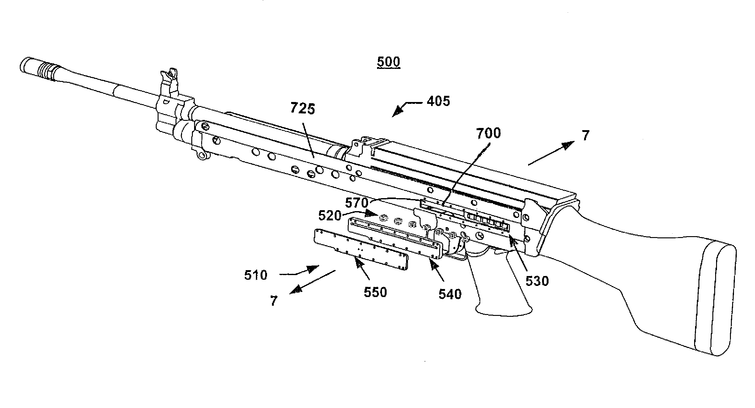
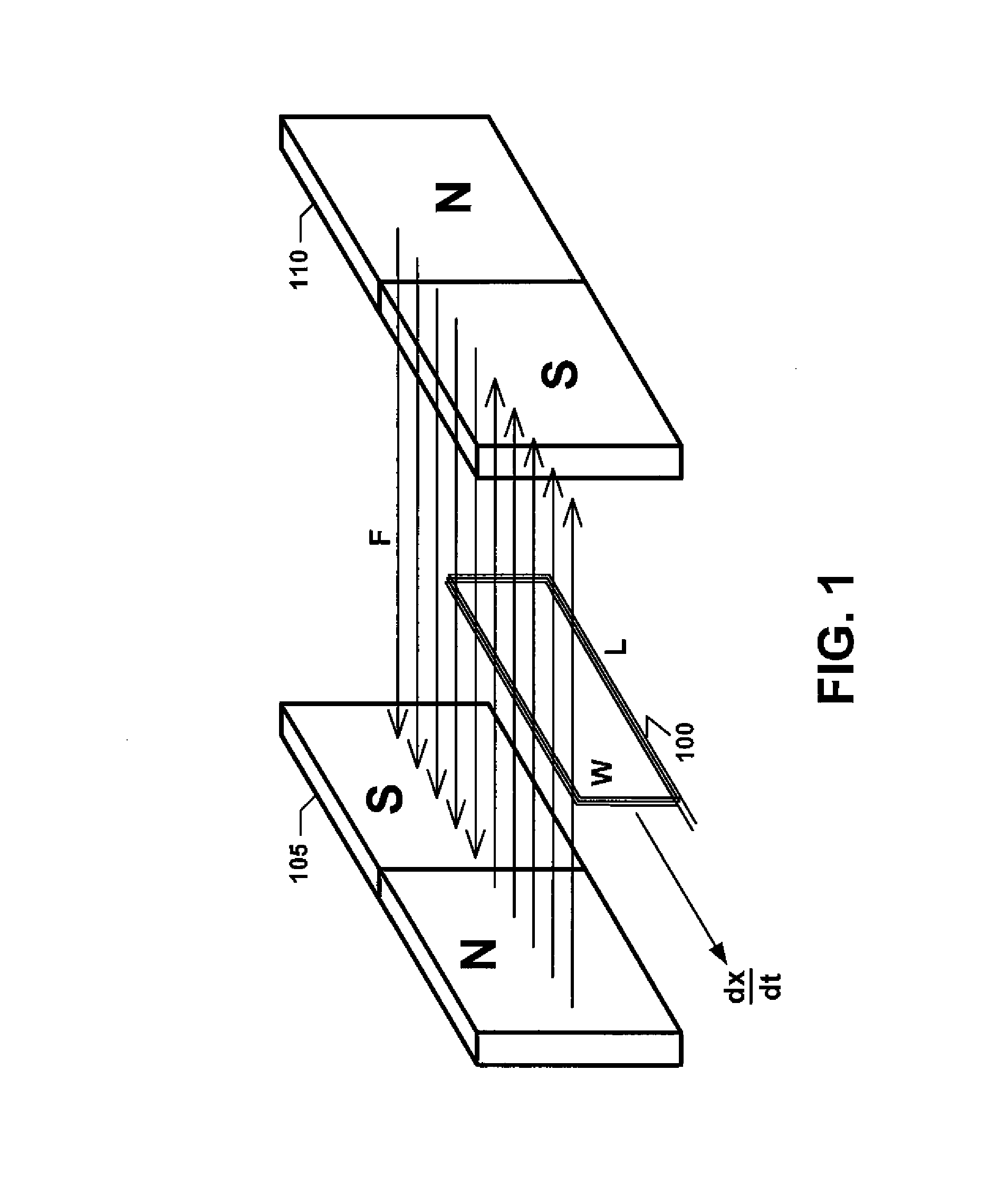
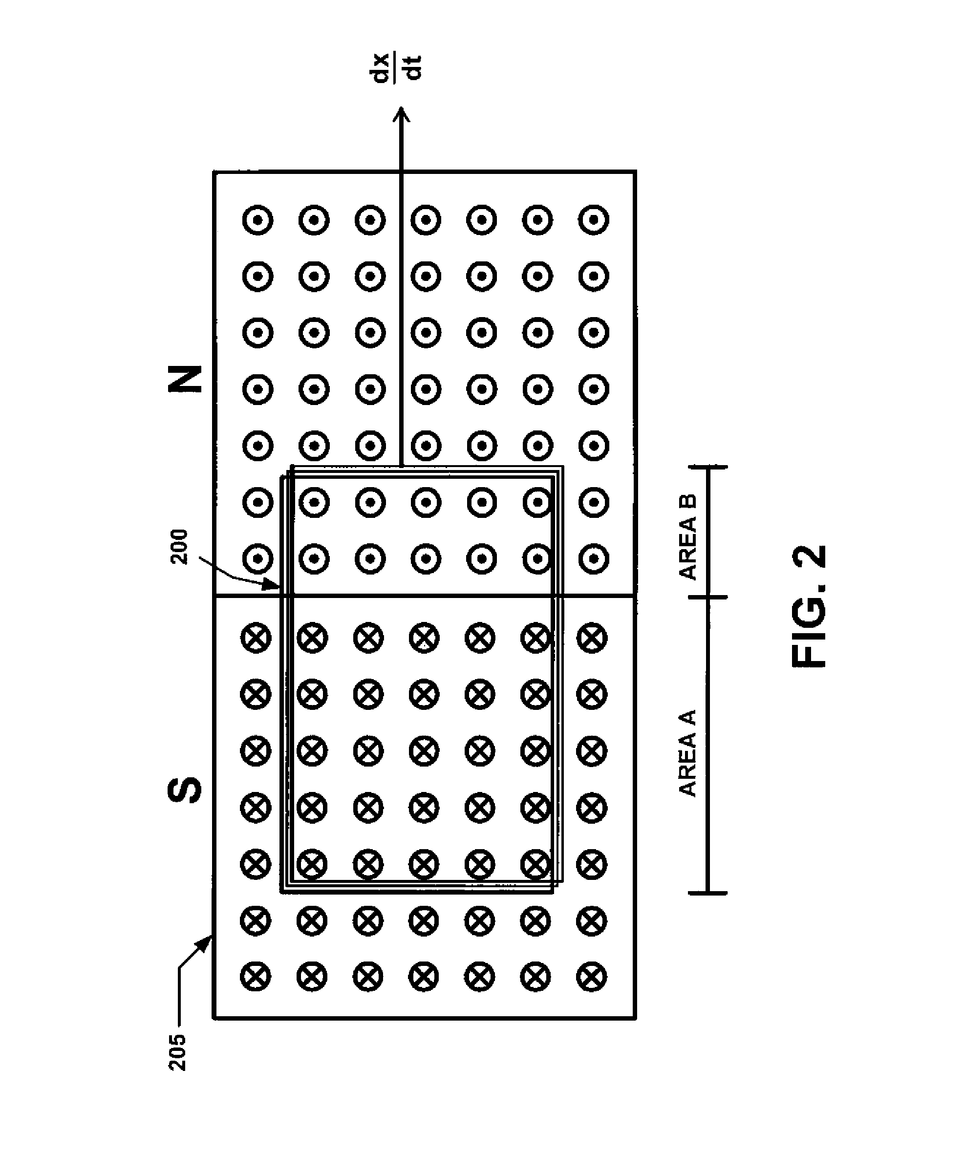
[0034]The present invention utilizes the potential to extract usable electrical energy from the kinetic energy associated with the operation of an automatic weapon. There are several challenges associated with practically capturing this power. From an energy conservation standpoint, however, the high cyclic rate of the weapon mechanism and the high speed linear action are favorable for energy capture by linear induction.

[0035]The general principle behind electricity production in generators, whether linear or rotary, is Faraday induction. Faraday induction is based on the concept that a conductor that moves relative to a surrounding magnetic field (or vice-versa) will experience an induced electrical current that is directly proportional to the relative speed. In a conventional generator, conductive loops of wire rotate within a fixed magnetic field created by either permanent or electro-magnets. Current is generated because the wire coils are changing their orientation with respect...


PUM


Abstract

A linear induction generator for use in a weapon system comprising a matrix of coils, a matrix of magnets, a spindle assembly, a matrix of coils, and a dust cover there over. This generator is mounted onto a weapon receiver of the weapon system to generate raw electric current. The raw current is then rectified and delivered to either a battery or directly to the electronic devices.

Description

CROSS-REFERENCE TO RELATED APPLICATIONS[0001]This application claims the benefit under 35 USC §119(e) of U.S. provisional patent application 61 / 485,736, filed on May 13, 2011, which is incorporated by reference in its entirety.GOVERNMENTAL INTEREST[0002]The invention described herein may be manufactured and used by, or for the Government of the United States for governmental purposes.FIELD OF THE INVENTION[0003]The present invention relates in general to the field of energy harvesting, particularly in small arms weapon systems, by linear induction. More specifically, this invention relates to resolving the persistent need of the modern war-fighter for readily available, portable electric power on the battlefield, by providing a self-powering or charging capability for the electronic devices.BACKGROUND OF THE INVENTION[0004]Equipment incorporating electronics components, such as magnifying optics, telecommunications / navigation equipment, night vision, range finders, laser designators...

Claims


Application Information

Patent Timeline
IPC IPC(8): F02B63/04F03G7/08
CPCF03G7/08F02B63/041F41A1/00F41A3/12F41A3/78
Inventor SMITH, ALEXANDER, PAUL
Owner UNITED STATES OF AMERICA THE AS REPRESENTED BY THE SEC OF THE ARMY
Learn More